
What Is a Busbar in Electrical Power Systems? Uses, Types & Safety Explained
Introduction: Why Busbars Matter in Modern Power Systems
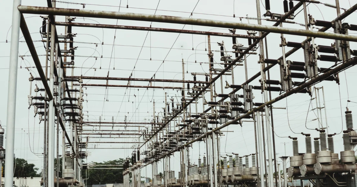
When you look inside any substation, distribution panel, switchgear, or renewable energy plant, one component quietly handles enormous levels of electrical energy: the busbar.
As you dive deeper into electrical engineering, you realize that busbars are more than just metal bars conducting electricity. They determine system reliability, short-circuit withstand capability, future expansion flexibility, and overall safety.
In this guide, you’ll understand:
- What a busbar is
- How it works
- The different types used in power systems
- Why substations rely on busbar arrangements
- How busbars are sized
- Safety requirements and failure risks
- Real-world applications and tools you may need
By the end, you’ll have a solid engineering-level understanding of busbars and how they shape modern electrical networks.
Table of Contents
What Is a Busbar?
A busbar is a conductive metallic bar or system of conductors used to collect, distribute, and transfer electrical power within a substation, panelboard, or industrial installation.
In technical terms, a busbar is:
- A low-impedance path designed to carry high current safely
- A mechanically rigid conductor able to withstand electrodynamic forces during faults
- A node for connecting circuits, transformers, breakers, and feeders
You typically see busbars made from:
- Copper (Cu) – high conductivity, best mechanical strength
- Aluminum (Al) – lighter and cheaper but larger in cross-section
Why Busbars Instead of Cables?
You use busbars instead of cables in medium and high-power systems because busbars provide:
- Higher short-circuit withstand capability
- Lower impedance → lower losses
- Better heat dissipation
- Easier installation and maintenance
- Higher mechanical strength
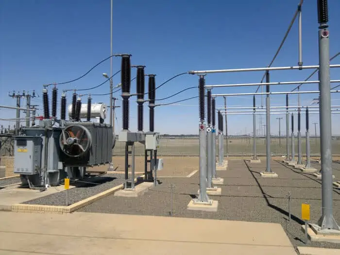
This makes busbars essential in:
- HV and MV substations
- Industrial switchgear
- Data centers
- EV charging hubs
- Renewable energy inverters and combiner boxes
How a Busbar Works
You can think of a busbar as the backbone of a power system node. Every incoming and outgoing line is connected to it through:
- Circuit breakers
- Disconnect switches
- Instrument transformers
- Surge arresters
- Protection relays
A busbar does not itself regulate the flow of electricity.
It simply provides a strong, low-impedance point to:
- Combine power
- Split power
- Redirect power
Power system protection is designed around the busbar’s behavior, including:
- Maximum short-circuit current
- Busbar differential protection
- Backup relay coordination
- Thermal withstand limits
Types of Busbars Used in Electrical Systems
Below are the main types you encounter in engineering practice.
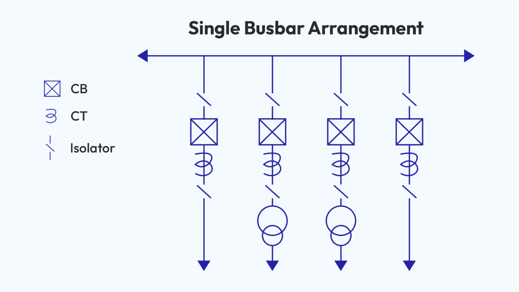
1. Single Busbar System
The simplest arrangement.
All feeders and transformers are connected to a single common bus.
Pros
- Low cost
- Easy design
- Minimal space required
Cons
- A fault on the bus trips the entire station
- No flexibility for maintenance
This is common in small distribution substations and industrial plants.
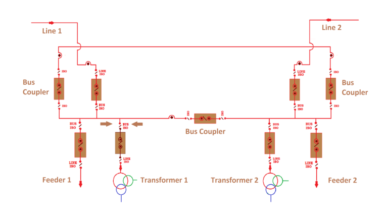
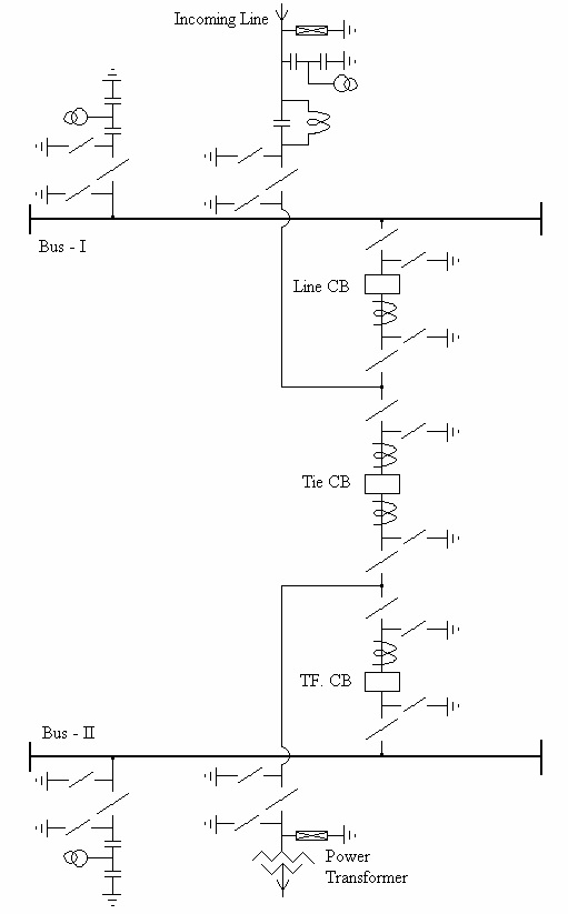
2. Double Busbar System
You have two separate buses (Main and Auxiliary).
Feeders can be switched between the two using bus couplers.
Pros
- High reliability
- Maintenance without shutdown
- Load transfer flexibility
Cons
- More breakers and switches
- Higher installation cost
Standard in large substations and critical industrial loads.
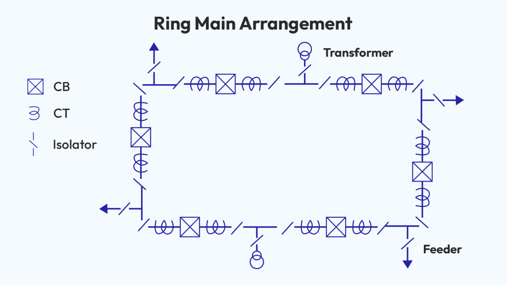
3. Ring Busbar System
Feeders form a complete ring, allowing power to flow from either direction.
Pros
- Excellent reliability
- Any section can be isolated
- Power still flows from the opposite side
Cons
- Complex protection
- Higher construction cost
Often used in transmission substations.
4. Breaker-and-Half Scheme
Each pair of feeders shares three breakers. Very common in modern HV substations.
Pros
- Extremely reliable
- Easy to expand
- Minimal interruption during faults
Cons
- High cost
- Sophisticated protection settings
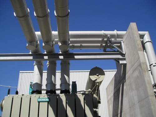
5. Isolated Phase Bus (IPB)
Used in power plants between generators and step-up transformers.
Each phase is:
- In a separate metal enclosure
- Air- or gas-insulated
- High current rated (10 kA+)
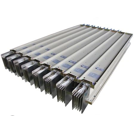
6. Bus Ducts / Sandwich Busbars
Used in:
- Data centers
- High-rise buildings
- EV charging stations
These are pre-engineered modular aluminum or copper bus systems.
Busbar Sizing and Current Rating
When you size a busbar, you consider:
1. Continuous Current Rating
Based on:
- Temperature rise limits
- Conductor material
- Cross-section
- Cooling method (air, oil, SF6)
2. Short-Circuit Rating
The busbar must survive:
- Thermal stress
- Electrodynamic forces
Formula for thermal withstand:
I² × t = k² × S²
Where:
- I = short-circuit current
- t = duration (usually 1s or 3s)
- k = material constant
- S = cross-section area
3. Voltage Level
Clearances and creepage distances change with:
- humidity
- pollution class
- insulation medium
4. Mechanical Strength
Fault currents generate forces of thousands of Newtons.
Busbar Faults and Safety Considerations
Busbars rarely fail, but when they do, the consequences are severe.
Common fault types
- Phase-to-phase short
- Phase-to-earth fault
- Flashover due to contamination
- Mechanical deformation
- Loose joints overheating
Busbar Protection
You typically use:
- Differential protection (87B)
- Distance relays
- Overcurrent protection
- CT supervision
Busbar protection must:
- Trip instantly (<20 ms)
- Correctly isolate the faulty section
- Avoid tripping healthy feeders
Real-World Applications of Busbars
You’ll find busbars in:
- Transmission substations (HV/MV)
- Large industrial switchgear
- Renewable energy plants (solar, wind)
- Electric vehicle fast-charging stations
- Data centers
- Power plants (generator buses)
They play critical roles in:
- Load transfer
- System stability
- Redundancy
- Fault clearing
Tools and Accessories You May Need
If you work with busbars, you often need tools such as:
- Busbar bending machines
- Hydraulic crimpers
- Insulation testers (megohmmeters)
- Torque wrenches
- Copper/aluminum cutters
- Heat-shrink tubing
You can find many affordable options on marketplaces like AliExpress if you need budget equipment for training or small installations.
Conclusion
Understanding busbars is essential if you want to master power system engineering.
They determine the safety, reliability, and flexibility of every electrical network — from small buildings to HV substations.
You now have a complete technical overview of:
- How busbars work
- Their different types and arrangements
- How they’re sized and protected
- The safety risks and failure modes
- Where they’re used in real-world systems
FAQ — Busbars in Electrical Power Systems
1. What is the main function of a busbar in a power system?
A busbar provides a low-impedance, mechanically strong connection point for distributing and collecting electric power inside substations, switchgear, and industrial installations. It allows multiple feeders, transformers, and breakers to connect at a single node.
2. Why do engineers prefer busbars over cables in high-power systems?
Busbars have:
- Higher short-circuit withstand capability
- Lower impedance (fewer losses)
- Better thermal performance
- Greater mechanical strength during faults
- Easier installation, expansion, and maintenance
This makes them ideal for MV/HV substations and high-current installations.
3. What materials are typically used to manufacture busbars?
Busbars are mainly made of:
- Copper (Cu) → high conductivity, strong, used in critical systems
- Aluminum (Al) → lighter, cheaper, but larger cross-section required
Choice depends on current rating, cost, and installation environment.
4. What are the most common busbar configurations in substations?
You’ll encounter:
- Single busbar
- Double busbar (Main & Auxiliary)
- Ring bus
- Breaker-and-Half
- Isolated Phase Bus (IPB)
- Bus duct or sandwich busbar systems
Each configuration balances cost, reliability, and operational flexibility.
5. How do you determine the correct busbar size?
Busbar sizing considers:
- Continuous current rating
- Allowable temperature rise
- Short-circuit thermal withstand (I²t)
- Electrodynamic forces during faults
- Material type (Cu/Al)
- Installation and cooling method
Engineers use standards such as IEC 61439 or IEEE C37.20.1.
6. What type of protection is applied to busbars?
The most important protection is busbar differential protection (87B).
You also see:
- Overcurrent relay backup
- Distance protection in some HV systems
- CT supervision to avoid false trips
Protection must clear faults extremely fast (<20 ms).
7. What are the main causes of busbar faults?
Common issues include:
- Contamination and surface flashover
- Loose or corroded joints
- Insulation failure
- Mechanical deformation under short-circuit forces
- Incorrect clearances
- Human error during maintenance
Busbar faults are rare but highly destructive.
8. Where are isolated-phase busbars used?
They are mainly used between:
- Power plant generators
and - Step-up transformers
IPBs handle very high currents (10–40 kA) and provide superior insulation and cooling.
9. Are busbars used in renewable energy and EV charging systems?
Yes. Modern energy systems rely heavily on busbars:
- Solar farms → DC combiner boxes, inverters
- Wind turbines → internal distribution
- EV fast-charging stations → high-current DC distribution
- Battery energy storage systems (BESS)
Busbars allow compact, low-loss, high-current DC and AC pathways.