How Potential Transformers Work: 4 Essential Roles Explained
Introduction: Why Understanding Potential Transformers Matters
Imagine standing near a humming power station. Thousands of volts course through the lines, yet the meter on the control panel shows just a few hundred volts. How is that possible? This is where Potential Transformers (PTs) come into play. These devices are silent heroes of electrical systems, working in the background to ensure safety, measurement, and control. If you’re working in energy, electrical maintenance, or engineering—or even if you’re just curious—grasping the role of potential transformers can enhance your understanding of how modern electricity grids operate and how they keep both people and equipment safe.
In this guide, you’ll discover how potential transformers work, what makes them indispensable, and the four essential roles they play in high-voltage environments.
Table of Contents
What Is a Potential Transformer?
Definition and Function
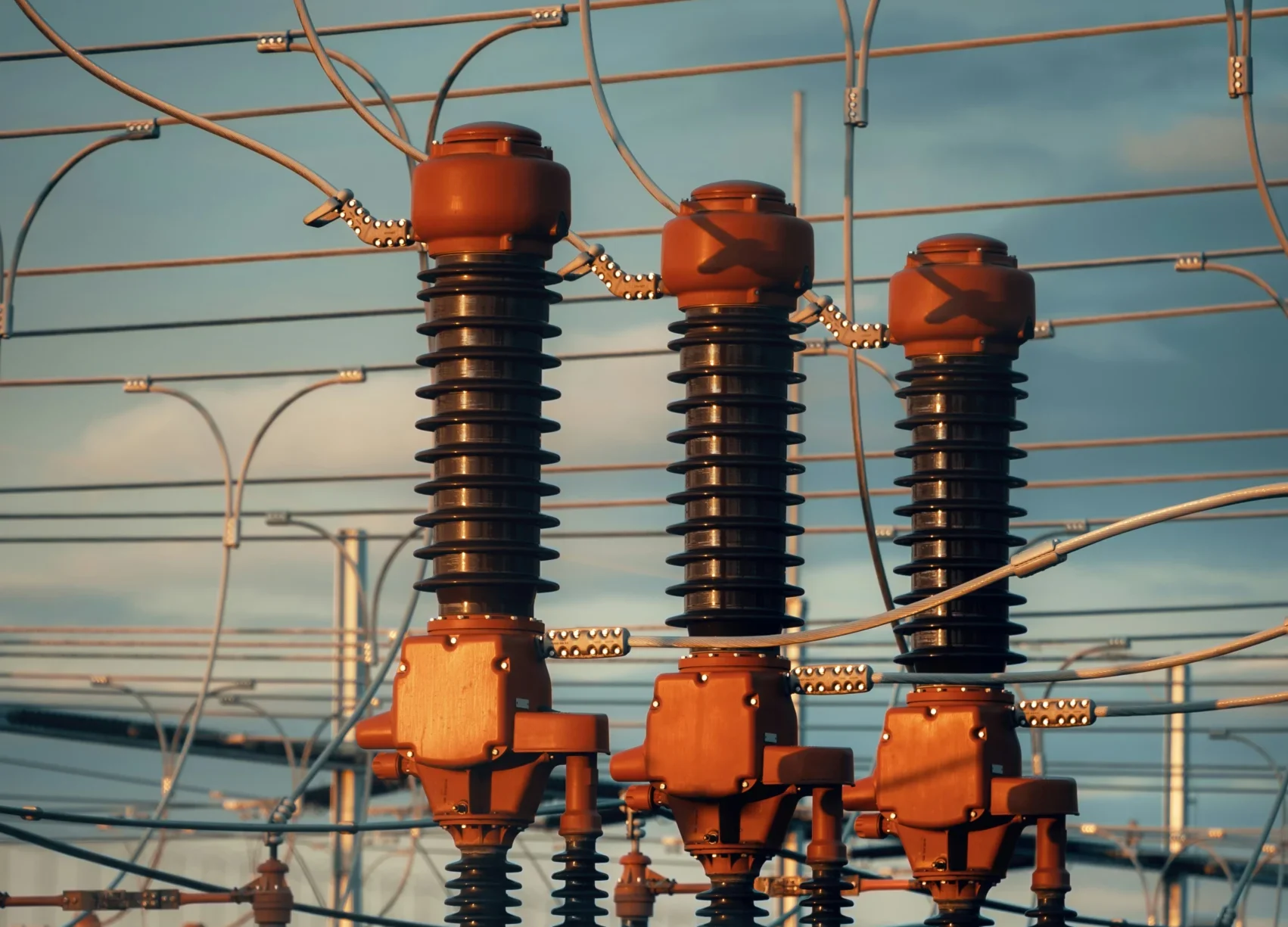
A Potential Transformer (PT) is a type of instrument transformer specifically designed to step down high voltages to a lower level that can be measured or monitored. It allows measuring instruments and protection relays to safely access voltage levels that would otherwise be too dangerous or damaging.
You might encounter potential transformers in power plants, industrial environments, or substations—essentially, anywhere that high-voltage electricity needs to be measured or monitored without direct exposure.
Why They Are Needed
- To protect sensitive equipment from exposure to dangerous voltage levels
- To allow accurate voltage readings for monitoring and billing
- To ensure safety for human operators by isolating high voltage circuits
Quick Technical Specs
- Typical Voltage Ratios: 11kV/110V, 420kV/110V
- Accuracy Class: 0.5, 1.0
- Insulation Types: Oil-filled, SF6 gas-insulated
How Potential Transformers Work
Basic Operating Principle
Potential transformers work on the principle of electromagnetic induction, just like a standard transformer. However, they are engineered with extreme precision and safety features to handle very high voltages.
- Primary winding connects to the high-voltage circuit.
- Secondary winding delivers a proportionally reduced voltage to meters or relays.
- The core ensures efficient magnetic flux transfer.
- Electrical isolation protects downstream systems.
Components of a PT
- Primary and Secondary Windings
- Magnetic Core
- High-voltage Insulation
- Protective Enclosure
Types of Potential Transformers
| Type | Application Area | Advantages |
|---|---|---|
| Electromagnetic PT | Substations, industrial setups | High accuracy and reliability |
| Capacitive Voltage PT | Transmission lines | Compact, cost-effective |
| Optical Voltage Transformer | Smart grids, advanced systems | Fast response, high bandwidth |
The 4 Essential Roles of Potential Transformers
1. Voltage Scaling for Metering
You need reliable and safe voltage readings for energy meters, load analysis, and system diagnostics. PTs reduce high voltage to a manageable level (like 110V) so that standard meters can operate without risk.
- Accurate voltage representation
- Enables consistent energy billing
- Helps in load balancing
2. Electrical Protection Systems
PTs work in tandem with protective relays, identifying dangerous conditions like overvoltage. The PT senses a spike, sends a scaled-down signal to the relay, which then commands the circuit breaker to disconnect the fault.
- Relay coordination
- Helps prevent electrical fires and equipment damage
- Integral to overvoltage and undervoltage protection
3. System Monitoring and Automation
SCADA systems rely on potential transformers to feed them real-time voltage data. You can’t control or automate what you can’t measure.
- Enables live voltage status
- Supports grid automation and load shedding
- Improves response time for grid anomalies
4. Isolation for Safety
PTs create an electrically isolated version of the high-voltage signal, protecting instruments and personnel.
- Prevents direct contact with high-voltage circuits
- Avoids accidental electrocution
- Provides a safer interface for analysis
Real-World Applications of Potential Transformers
In Power Plants
- Monitor voltage output from generators
- Ensure synchronization with the grid
In Substations
- Measure incoming and outgoing line voltages
- Coordinate protection schemes
In Industrial Settings
- Track power quality and stability
- Protect machinery from voltage irregularities
Common Issues and Maintenance Tips
Common Issues
- Insulation Deterioration: Caused by temperature and environmental exposure
- Core Saturation: Results in distorted voltage readings
- Short Circuits in Secondary Windings: Causes inaccurate readings
Maintenance Tips
- Periodic insulation resistance testing
- Visual inspection for oil leaks or swelling
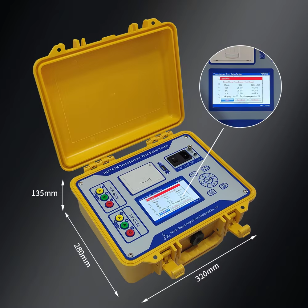
- Calibration with ratio testing devices
- Keeping terminals clean and dry
Conclusion: Why You Should Care About Potential Transformers
Whether you’re managing an industrial grid or studying for your electrical engineering exam, understanding potential transformers equips you to engage safely and smartly with high-voltage systems. They don’t just lower voltages—they enable everything from precise billing to life-saving protection systems. Each of the four essential roles they play makes your electrical system more reliable, safer, and easier to control.
So the next time you walk past a substation or analyze grid data, remember that there’s a potential transformer quietly making that possible.
FAQs About Potential Transformers
What is the main function of a potential transformer?
A Potential Transformer is primarily used to reduce high voltage to a lower, safer level so it can be measured and monitored safely.
How do PTs differ from current transformers (CTs)?
While PTs deal with voltage, current transformers scale down current for measurement and protection. Both are essential in power system instrumentation.
Can PTs be used for low-voltage circuits?
PTs are generally not designed for low-voltage applications. Their insulation and structure are meant for medium to high-voltage systems.
What causes a PT to fail?
- Moisture ingress
- Insulation breakdown
- Core overheating
How do I test if a PT is working correctly?
Use a voltage ratio test set to compare input and output. Also, check insulation resistance and inspect visually for any physical damage.


