
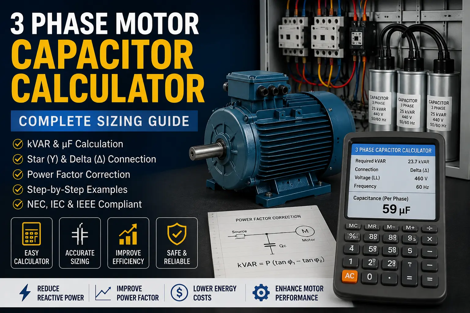
3 Phase Motor Capacitor Calculator: Complete Sizing Guide
Introduction
Choosing the correct capacitor for a three-phase motor requires more than simply matching a capacitor to the motor’s horsepower or kilowatt rating.
The correct capacitor size depends on several electrical parameters, including:
- Motor active power.
- Existing power factor.
- Desired power factor.
- Supply voltage.
- Supply frequency.
- Capacitor connection.
- Motor operating load.
- Harmonic distortion.
- Switching arrangement.
This is why a 3 phase motor capacitor calculator is useful for electricians, electrical technicians, engineers, students, and industrial maintenance professionals.
However, there is an important distinction to understand before performing any calculation.
A conventional three-phase induction motor connected to a three-phase supply does not normally require a capacitor to operate. The three-phase supply already produces the rotating magnetic field required by the motor.
In this application, a capacitor is commonly used for power-factor correction.
A different calculation applies when a three-phase motor is being operated from a single-phase supply using a capacitor. That is a motor-conversion application and should not be confused with conventional three-phase power-factor correction.
This guide explains both concepts, but the main calculations focus on three-phase motor power-factor correction.
Table of Contents
What Is a 3 Phase Motor Capacitor?
A three-phase induction motor consumes both active power and reactive power.
Active power performs useful work and is measured in kilowatts (kW).
Reactive power is associated with the magnetic field of inductive equipment and is measured in kilovolt-amperes reactive (kVAR).
The motor’s apparent power is:
S = √(P² + Q²)
Where:
- S = apparent power in kVA
- P = active power in kW
- Q = reactive power in kVAR
The power factor is:
PF = P / S
A motor with a low power factor requires more current from the electrical supply for the same amount of useful active power.
A capacitor provides leading reactive power that can offset part of the motor’s lagging reactive power.
The result is a better overall power factor and lower reactive current in the upstream electrical system.
Does a Three-Phase Motor Need a Capacitor?
A standard three-phase induction motor connected to a balanced three-phase supply normally does not need a capacitor to start or run.
The three-phase supply itself creates the rotating magnetic field.
A capacitor may nevertheless be installed for:
- Power-factor correction.
- Reactive-power compensation.
- Reduction of upstream reactive current.
- Improvement of electrical system utilization.
- Reduction of some I²R losses associated with unnecessary reactive current.
The basic arrangement can be represented as:
Three-Phase Supply
     L1 L2 L3
       │ │ │
       ▼ ▼ ▼
┌─────────────────┐
│ Motor Protection│
│ & Switching     │
└────────┬────────┘
         │
         ▼
┌─────────────────┐
│ 3-Phase Motor   │
└─────────────────┘
         │
         │
         ▼
┌─────────────────┐
│ Capacitor Bank  │
│ Power Factor    │
│ Correction      │
└─────────────────┘
The exact switching and connection arrangement must be designed for the particular installation.
Why Correct the Power Factor of a Motor?
Consider a motor consuming 30 kW with a power factor of 0.75.
Its apparent power is:
S = P / PF
Substitute the values:
S = 30 / 0.75
S = 40 kVA
Now suppose the power factor is improved to 0.95.
S = 30 / 0.95
S ≈ 31.58 kVA
The motor still requires approximately 30 kW of active power, but the electrical system now supplies considerably less apparent power.
Power-factor correction can therefore help:
- Reduce line current.
- Reduce transformer loading caused by reactive current.
- Improve system capacity utilization.
- Reduce conductor losses associated with reactive current.
- Reduce utility power-factor penalties where applicable.
- Improve overall electrical efficiency.
However, capacitor correction does not eliminate the motor’s mechanical energy requirement.
Inputs Required for a 3 Phase Motor Capacitor Calculator
A useful motor capacitor sizing calculator should require the following information.
| Parameter | Symbol | Unit |
|---|---|---|
| Motor active power | P | kW |
| Existing power factor | PF₁ | Decimal |
| Target power factor | PF₂ | Decimal |
| Line-to-line voltage | V | V |
| Frequency | f | Hz |
| Capacitor connection | — | Star or Delta |
| Required reactive power | Qc | kVAR |
| Capacitance | C | µF |
For the most accurate result, use the motor’s actual operating power rather than automatically using the motor’s nameplate rating.
3 Phase Motor Capacitor Calculation Formula
The fundamental formula for power-factor correction is:
Qc = P × (tan φ₁ − tan φ₂)
Where:
- Qc = required capacitor reactive power in kVAR
- P = motor active power in kW
- φ₁ = existing power-factor angle
- φ₂ = desired power-factor angle
The angles are calculated using:
φ₁ = cos⁻¹(PF₁)
and:
φ₂ = cos⁻¹(PF₂)
Therefore, the complete formula can be written as:
Qc = P × [tan(cos⁻¹(PF₁)) − tan(cos⁻¹(PF₂))]
This formula is the foundation of a 3 phase motor capacitor calculation for power-factor correction.
Understanding the Formula Before Calculating
Suppose:
- Motor power = 50 kW
- Existing PF = 0.78
- Target PF = 0.95
We first calculate the existing power-factor angle.
φ₁ = cos⁻¹(0.78)
φ₁ ≈ 38.74°
Now calculate its tangent:
tan(38.74°) ≈ 0.803
Next calculate the target angle.
φ₂ = cos⁻¹(0.95)
φ₂ ≈ 18.19°
Then:
tan(18.19°) ≈ 0.329
Now we have everything required to calculate the capacitor’s reactive power.
Complete Engineering Example 1: Calculate Required kVAR
Consider a three-phase motor with:
- Motor active power = 50 kW
- Existing power factor = 0.78
- Target power factor = 0.95
Step 1: Calculate the Existing Power-Factor Angle
Use:
φ₁ = cos⁻¹(PF₁)
Substitute:
φ₁ = cos⁻¹(0.78)
Therefore:
φ₁ ≈ 38.74°
Step 2: Calculate tan φ₁
tan φ₁ = tan(38.74°)
Therefore:
tan φ₁ ≈ 0.803
Step 3: Calculate the Target Power-Factor Angle
Use:
φ₂ = cos⁻¹(PF₂)
Substitute:
φ₂ = cos⁻¹(0.95)
Therefore:
φ₂ ≈ 18.19°
Step 4: Calculate tan φ₂
tan φ₂ = tan(18.19°)
Therefore:
tan φ₂ ≈ 0.329
Step 5: Calculate Required Capacitor kVAR
Use:
Qc = P × (tan φ₁ − tan φ₂)
Substitute the values:
Qc = 50 × (0.803 − 0.329)
First calculate the difference:
0.803 − 0.329 = 0.474
Now multiply by motor power:
Qc = 50 × 0.474
Therefore:
Qc = 23.7 kVAR
Final Result
Required capacitor compensation ≈ 23.7 kVAR
A practical installation would normally use an available standard capacitor-bank rating close to the calculated requirement, subject to the motor’s actual load and the complete electrical-system design.
Calculating Capacitance in Microfarads
After calculating the required kVAR, you may need to determine the corresponding capacitance in µF.
The formula depends on whether the capacitors are connected in delta or star.
For a delta-connected capacitor bank:
C = Qc / [3 × 2π × f × V²]
Where:
- C = capacitance of each capacitor in farads (F)
- Qc = total capacitor reactive power in VAR
- f = frequency in Hz
- V = line-to-line voltage in volts
Remember an important conversion:
1 kVAR = 1,000 VAR
Therefore:
23.7 kVAR = 23,700 VAR
Complete Engineering Example 2: Delta-Connected Capacitor
Use the previous example:
- Required reactive power = 23.7 kVAR
- Voltage = 460 V
- Frequency = 60 Hz
- Connection = Delta
Step 1: Convert kVAR to VAR
Qc = 23.7 × 1,000
Qc = 23,700 VAR
Step 2: Write the Formula
For delta:
C = Qc / [3 × 2π × f × V²]
Step 3: Substitute the Values
C = 23,700 / [3 × 2π × 60 × 460²]
Step 4: Calculate the Voltage Squared
460² = 211,600
Therefore:
C = 23,700 / [3 × 2π × 60 × 211,600]
Step 5: Calculate the Denominator
The denominator is approximately:
3 × 2π × 60 × 211,600 ≈ 238,950,000
Therefore:
C ≈ 23,700 / 238,950,000
C ≈ 0.0000992 F
Step 6: Convert Farads to Microfarads
Use:
1 F = 1,000,000 µF
Therefore:
C = 0.0000992 × 1,000,000
C ≈ 99.2 µF
Final Result
For this theoretical example:
Required capacitance ≈ 99.2 µF per capacitor
for a balanced delta-connected capacitor bank.
This means the calculated theoretical arrangement is approximately:
3 × 99.2 µF capacitors connected in delta
In practice, the final capacitor selection must be based on available standard ratings, capacitor voltage rating, tolerances, operating conditions, harmonics, switching requirements, and manufacturer specifications.
Why the Previous 59 µF Calculation Was Wrong
It is important to highlight this because it is an easy calculation error.
For:
- Qc = 23.7 kVAR
- V = 460 V
- f = 60 Hz
- Delta connection
the correct formula is:
C = 23,700 / [3 × 2π × 60 × 460²]
The result is:
C ≈ 99.2 µF
not 59 µF.
The approximately 59 µF value would correspond to a different combination of reactive power, voltage, and frequency.
This demonstrates why every step of a 3 phase motor capacitor calculation should be shown rather than presenting only the final number.
Star-Connected Capacitor Calculation
For a star-connected capacitor bank, the formula is:
C = Qc / [2π × f × V²]
Where:
- C = capacitance per capacitor in farads
- Qc = total reactive power in VAR
- f = frequency in Hz
- V = line-to-line voltage in volts
Compare this with the delta formula:
Delta:
CΔ = Qc / [3 × 2π × f × V²]
Star:
CY = Qc / [2π × f × V²]
Therefore:
CY = 3 × CΔ
For the same total kVAR, line voltage, and frequency, each star-connected capacitor theoretically requires three times the capacitance of each delta-connected capacitor.
Star vs Delta Capacitor Connection
| Parameter | Delta Connection | Star Connection |
|---|---|---|
| Capacitor voltage | Line-to-line voltage | Line-to-neutral equivalent |
| Formula | Qc / [3 × 2π × f × V²] | Qc / [2π × f × V²] |
| Capacitance per capacitor | Lower | Higher |
| Number of capacitors | 3 | 3 |
| Common application | Three-phase capacitor banks | Specific system designs |
| Voltage stress | Higher | Lower |
The actual connection should be selected according to the system design and capacitor manufacturer’s requirements.
Engineering Example 3: 400 V, 50 Hz Motor
Consider a motor operating at:
- Active power = 30 kW
- Existing PF = 0.80
- Target PF = 0.95
- Supply voltage = 400 V
- Frequency = 50 Hz
- Capacitor connection = Delta
Step 1: Calculate Existing Angle
φ₁ = cos⁻¹(0.80)
φ₁ ≈ 36.87°
Therefore:
tan φ₁ ≈ 0.75
Step 2: Calculate Target Angle
φ₂ = cos⁻¹(0.95)
φ₂ ≈ 18.19°
Therefore:
tan φ₂ ≈ 0.329
Step 3: Calculate Required kVAR
Qc = P × (tan φ₁ − tan φ₂)
Qc = 30 × (0.75 − 0.329)
Qc = 30 × 0.421
Qc ≈ 12.63 kVAR
Therefore:
Required capacitor compensation ≈ 12.63 kVAR
Step 4: Convert to VAR
Qc = 12.63 × 1,000
Qc = 12,630 VAR
Step 5: Calculate Capacitance
For delta:
C = Qc / [3 × 2π × f × V²]
Substitute:
C = 12,630 / [3 × 2π × 50 × 400²]
Calculate voltage squared:
400² = 160,000
Therefore:
C = 12,630 / [3 × 2π × 50 × 160,000]
The result is approximately:
C ≈ 0.0000839 F
Convert to microfarads:
C = 0.0000839 × 1,000,000
C ≈ 83.9 µF
Final Result
Required capacitance ≈ 84 µF per capacitor
for the theoretical delta-connected capacitor bank.
Why Motor Load Is Important
One of the most common mistakes in 3 phase motor capacitor sizing is using the motor’s full nameplate power without considering actual operating load.
For example, a 30 kW motor may frequently operate at only 15 kW.
If the capacitor is permanently sized for full-load compensation, it may provide excessive compensation when the motor operates at light load.
This can produce an undesirable leading power factor.
The problem becomes particularly important for motors that:
- Operate under variable loads.
- Frequently start and stop.
- Run unloaded.
- Drive variable production machinery.
- Operate intermittently.
- Work alongside other large inductive loads.
For these installations, automatic capacitor switching or centralized automatic power-factor correction may be preferable.
Fixed Capacitor vs Automatic Capacitor Bank
| Feature | Fixed Capacitor | Automatic Capacitor Bank |
|---|---|---|
| Cost | Lower | Higher |
| Control | Simple | Automatic |
| Variable load | Less suitable | More suitable |
| Overcorrection risk | Higher | Lower |
| Installation | Simple | More complex |
| Maintenance | Low | Moderate |
| Best application | Stable loads | Variable loads |
A fixed capacitor can be appropriate when the motor has a relatively stable load.
An automatic capacitor bank is generally better when reactive power changes significantly during operation.
Where Should the Capacitor Be Installed?
There are three common approaches.
Individual Motor Compensation
A capacitor is installed directly with an individual motor.
Advantages:
- Reactive power is compensated close to the motor.
- Upstream reactive current can be reduced.
- The capacitor can be associated with the motor’s operation.
The switching arrangement must be properly designed.
Group Compensation
One capacitor bank serves several motors.
This can be economical when multiple motors operate together.
However, the operating pattern of the motors should be evaluated carefully.
Centralized Compensation
A capacitor bank is installed at a main distribution board.
This approach is particularly useful for facilities with:
- Multiple motors.
- Variable reactive demand.
- Automatic power-factor control.
- Centralized electrical distribution.
Capacitors and Harmonics
Power-factor correction becomes more complicated when the electrical installation contains nonlinear loads.
Examples include:
- Variable-frequency drives.
- UPS systems.
- Rectifiers.
- Welding machines.
- Large electronic converters.
- Switched-mode power supplies.
These loads can produce harmonic currents.
Capacitors can interact with system inductance and potentially create resonance conditions.
Possible consequences include:
- Excessive capacitor current.
- Capacitor overheating.
- Increased voltage distortion.
- Protection trips.
- Reduced capacitor life.
- Resonance problems.
For installations with significant harmonic distortion, engineers may need to consider:
- Detuned capacitor banks.
- Harmonic filters.
- Reactor-capacitor combinations.
- Active harmonic filters.
- Power-quality measurements.
Do not install a large capacitor bank into a harmonic-rich industrial system without evaluating the system impedance and resonance risk.
Motor Capacitor vs Power-Factor-Correction Capacitor
These terms are often confused.
| Feature | Motor Capacitor | Power-Factor-Correction Capacitor |
|---|---|---|
| Main purpose | Starting/running phase-shift function in applicable motor configurations | Reactive-power compensation |
| Typical application | Single-phase or converted motor systems | Three-phase electrical systems |
| Main calculation | Motor-specific | kW, PF, kVAR |
| Typical rating | µF | kVAR or µF |
| Main concern | Motor winding characteristics | Electrical system reactive power |
A standard three-phase motor supplied by a three-phase source should not automatically be given a capacitor using a single-phase motor capacitor formula.
IEC 60252-1 covers AC motor capacitors, including applications involving asynchronous motors supplied from single-phase systems.
For low-voltage power-factor-correction capacitors, IEC 60831-1 is relevant.
Can a Capacitor Run a Three-Phase Motor From Single-Phase Power?
A capacitor can sometimes be used in a Steinmetz-type arrangement to operate a three-phase induction motor from a single-phase supply.
However, this is not the same calculation as power-factor correction.
The motor may experience:
- Reduced starting torque.
- Reduced available power.
- Unbalanced winding currents.
- Increased temperature.
- Lower efficiency.
- Reduced starting reliability.
The capacitor value depends on:
- Motor power.
- Motor voltage.
- Frequency.
- Winding connection.
- Motor design.
- Required torque.
- Operating load.
For industrial applications, a properly selected variable-frequency drive or phase converter may provide a more appropriate solution.
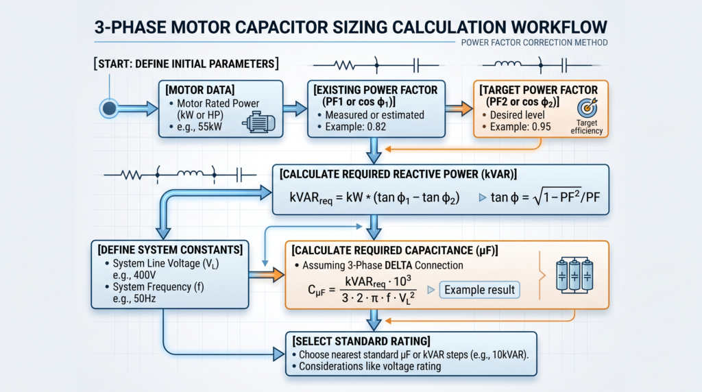
Practical 3 Phase Motor Capacitor Calculation Workflow
A reliable calculator should follow this sequence.
Step 1 — Enter Motor Power
Enter the motor’s actual active power in kW.
If the motor power is given in horsepower:
P(kW) = HP × 0.746
For example:
20 HP × 0.746 = 14.92 kW
If motor efficiency is known, electrical input power can be estimated:
P(input) = P(output) / η
where η is efficiency expressed as a decimal.
Step 2 — Enter Existing Power Factor
For example:
PF₁ = 0.78
Use measured operating power factor whenever possible.
Step 3 — Enter Target Power Factor
For example:
PF₂ = 0.95
The target should be selected based on the installation’s engineering requirements.
Step 4 — Calculate the Existing Reactive Power
Use:
Q₁ = P × tan(cos⁻¹ PF₁)
Step 5 — Calculate the Target Reactive Power
Use:
Q₂ = P × tan(cos⁻¹ PF₂)
Step 6 — Calculate Required Capacitor kVAR
Use:
Qc = Q₁ − Q₂
or directly:
Qc = P × [tan(cos⁻¹ PF₁) − tan(cos⁻¹ PF₂)]
Step 7 — Convert kVAR to VAR
Qc(VAR) = Qc(kVAR) × 1,000
Step 8 — Select Capacitor Connection
Choose:
- Delta
- Star
Step 9 — Calculate Capacitance
For delta:
C = Qc / [3 × 2π × f × V²]
For star:
C = Qc / [2π × f × V²]
Step 10 — Convert to µF
C(µF) = C(F) × 1,000,000
Quick Formula Reference
| Calculation | WordPress-Friendly Formula |
|---|---|
| Apparent power | S = P / PF |
| Power-factor angle | φ = cos⁻¹(PF) |
| Reactive power | Q = P × tan φ |
| Required capacitor kVAR | Qc = P × (tan φ₁ − tan φ₂) |
| Delta capacitance | C = Qc / [3 × 2π × f × V²] |
| Star capacitance | C = Qc / [2π × f × V²] |
| Angular frequency | ω = 2πf |
| Capacitive reactance | Xc = 1 / (2πfC) |
| HP to kW | P = HP × 0.746 |
| Motor input power | P(input) = P(output) / η |
Important: When calculating capacitance, Qc must be expressed in VAR, not kVAR.
Common 3 Phase Motor Capacitor Sizing Mistakes
1. Using a Single-Phase Formula
Do not use a single-phase motor capacitor formula for a three-phase power-factor-correction application.
2. Using Horsepower Alone
Motor horsepower does not determine capacitor size by itself.
You also need the operating power factor and target power factor.
3. Using Nameplate Power Without Considering Load
A motor rated at 30 kW may not consume 30 kW continuously.
Actual operating conditions should be evaluated.
4. Choosing an Excessively High Target PF
A target PF of 1.00 is not necessarily the correct engineering objective.
Overcorrection can create a leading power factor.
5. Ignoring Harmonics
Industrial facilities containing VFDs and other nonlinear loads require additional analysis before installing large capacitor banks.
6. Forgetting the Voltage
Capacitance depends strongly on voltage.
The voltage term is squared:
C ∝ 1 / V²
Therefore, a change in system voltage can significantly change the required capacitance.
7. Forgetting Frequency
Capacitive reactive power also depends on frequency.
A capacitor designed for 50 Hz should not automatically be treated as equivalent at 60 Hz.
8. Confusing kVAR and µF
kVAR describes reactive-power output under specified conditions.
µF describes capacitance.
You need voltage and frequency to convert between them.
Safety Considerations
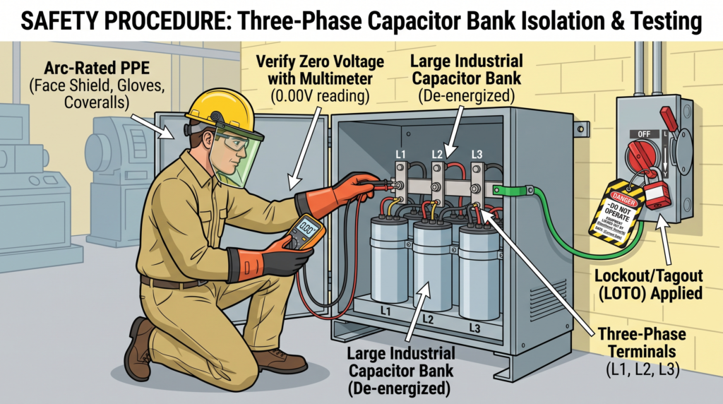
Capacitors can store electrical energy after the supply has been disconnected.
Never assume that switching off a circuit breaker automatically makes a capacitor safe.
Before servicing capacitor equipment:
- Isolate the electrical supply.
- Apply the appropriate lockout/tagout procedure.
- Prevent unauthorized energization.
- Allow the capacitor’s discharge system to operate.
- Verify absence of voltage.
- Follow the manufacturer’s discharge procedure.
- Test the capacitor terminals using suitable equipment.
- Use appropriate PPE.
- Follow the applicable electrical safety procedures.
- Confirm the circuit is safe before beginning work.
Potential hazards include:
- Stored electrical energy.
- Arc flash.
- Short circuits.
- Capacitor failure.
- Overvoltage.
- Thermal damage.
- Switching transients.
- Harmonic currents.
For US installations, consult the applicable NEC requirements and the requirements of the authority having jurisdiction.
For European and other IEC-based installations, consult the applicable IEC standards and national implementation requirements.
NEC, IEC and IEEE Considerations
The capacitor calculation itself does not determine whether an installation is code compliant.
The complete design must consider applicable electrical standards.
NEC
For US installations, the applicable edition of the National Electrical Code should be consulted for:
- Capacitor installations.
- Motor circuits.
- Conductors.
- Overcurrent protection.
- Disconnecting means.
- Grounding and bonding.
- Equipment installation.
Always use the NEC edition adopted by the jurisdiction where the installation is located.
IEC 60252-1
IEC 60252-1 addresses AC motor capacitors and includes requirements related to performance, testing, rating, safety, installation, and operation.
It is particularly relevant to motor-capacitor applications.
IEC 60831-1
IEC 60831-1 addresses self-healing shunt power capacitors for AC systems up to and including 1,000 V and is relevant to low-voltage power-factor-correction applications.
IEC 61921
IEC 61921 addresses low-voltage AC shunt capacitor banks used for power-factor correction and associated switchgear/controlgear arrangements.
IEEE 18
IEEE 18 covers shunt power capacitors for specified AC transmission and distribution applications.
For industrial projects, engineers should identify the standards that actually apply to the specific equipment and voltage level rather than assuming that every capacitor installation is covered by the same standard.
When Should You Avoid a Fixed Capacitor?
A fixed capacitor may not be appropriate when:
- Motor load varies significantly.
- The motor frequently starts and stops.
- Multiple motors are switched independently.
- VFDs represent a significant portion of the installation.
- Harmonic distortion is high.
- Resonance is possible.
- Power factor changes substantially during production.
- Dynamic compensation is required.
In these situations, consider:
- Automatic capacitor banks.
- Detuned capacitor banks.
- Harmonic filters.
- Active power-factor correction.
- Other power-quality solutions.
A power-quality study may be necessary before selecting the equipment.
How a 3 Phase Motor Capacitor Calculator Should Work
A professional Zoneleec calculator should provide a clear sequence rather than returning a single number.
Input Section
The user enters:
- Motor power.
- Power unit.
- Existing PF.
- Target PF.
- Voltage.
- Frequency.
- Capacitor connection.
Calculation Section
The calculator should display:
1. Existing reactive power
2. Target reactive power
3. Required compensation
4. Required kVAR
5. Required capacitance
6. Capacitor current
Result Section
For example:
Motor Power: 50 kW
Existing PF: 0.78
Target PF: 0.95
Voltage: 460 V
Frequency: 60 Hz
Connection: Delta
Required Compensation: 23.7 kVAR
Calculated Capacitance: ≈ 99.2 µF per capacitor
this transparent approach allows users to verify every calculation.
Frequently Asked Questions
1. What is a 3 phase motor capacitor calculator?
A 3 phase motor capacitor calculator determines the amount of reactive-power compensation required to improve the power factor of a three-phase motor and can convert the required kVAR into capacitance in microfarads.
2. Do three-phase motors need capacitors?
A standard three-phase induction motor connected to a three-phase supply normally does not need a capacitor to operate. A capacitor may be installed for power-factor correction.
3. How do you calculate capacitor size for a three-phase motor?
First calculate the required reactive compensation:
Qc = P × (tan φ₁ − tan φ₂)
Then convert the required kVAR into capacitance according to the capacitor connection.
For delta:
C = Qc / [3 × 2π × f × V²]
For star:
C = Qc / [2π × f × V²]
Remember to convert kVAR to VAR before calculating capacitance in farads.
4. Is capacitor size measured in kVAR or µF?
Both are used.
kVAR describes reactive-power compensation.
µF describes physical capacitance.
The relationship between them depends on voltage, frequency, and capacitor connection.
5. Is star or delta better for a three-phase capacitor?
Neither is universally better.
The correct configuration depends on system voltage, capacitor ratings, insulation requirements, reactive-power requirements, and the manufacturer’s design.
6. Can a capacitor run a three-phase motor from single-phase power?
A capacitor can sometimes be used in a Steinmetz-type configuration, but this is a different application from normal power-factor correction.
Motor performance can be reduced, and the motor may experience lower torque and increased heating.
7. Can a motor capacitor be too large?
Yes.
An oversized capacitor can cause overcorrection and produce a leading power factor.
It may also contribute to undesirable voltage or resonance conditions.
8. What standards apply to three-phase motor capacitors?
The applicable standard depends on the application.
IEC 60252-1 is relevant to AC motor capacitors.
IEC 60831-1 applies to low-voltage shunt power capacitors used for applications such as power-factor correction.
IEC 61921 addresses low-voltage power-factor-correction capacitor banks.
IEEE 18 covers specified shunt power capacitor applications.
US installations should also comply with the applicable NEC requirements.
Final Conclusion
Correct 3 phase motor capacitor sizing requires more than selecting a capacitor based on motor horsepower.
For a conventional three-phase induction motor, the capacitor is generally used to provide reactive-power compensation and improve the power factor.
The first calculation is the required capacitor reactive power:
Qc = P × (tan φ₁ − tan φ₂)
where:
φ₁ = cos⁻¹(PF₁)
and:
φ₂ = cos⁻¹(PF₂)
After determining the required kVAR, convert it to capacitance.
For a delta-connected capacitor bank:
C = Qc / [3 × 2π × f × V²]
For a star-connected capacitor bank:
C = Qc / [2π × f × V²]
Always convert kVAR to VAR before calculating capacitance in farads.
For example, a 50 kW motor operating at 0.78 power factor and corrected to 0.95 requires approximately:
23.7 kVAR of reactive compensation
At 460 V and 60 Hz with a delta-connected capacitor bank, this corresponds theoretically to approximately:
99.2 µF per capacitor
The calculation is only the starting point.
Before installing the capacitor, evaluate actual motor loading, voltage, frequency, capacitor ratings, harmonics, switching behavior, protection, discharge requirements, temperature, and applicable electrical standards.
For fixed and stable loads, individual or fixed compensation may be appropriate. For variable industrial loads, an automatic capacitor bank can provide better control. In systems with significant harmonics, detuned capacitor banks or harmonic-filtering solutions may be required.
The most important principle is:
Calculate the required kVAR first, convert kVAR to µF second, and validate the complete electrical installation before selecting the final capacitor.
That approach provides a technically sound foundation for electricians, technicians, engineers, students, and industrial professionals using a 3 phase motor capacitor calculator.
Technical References
- IEC 60252-1 — AC motor capacitors.
- IEC 60831-1 — Low-voltage self-healing shunt power capacitors.
- IEC 61921 — Low-voltage power-factor-correction capacitor banks.
- IEEE 18 — Shunt power capacitors.
- National Electrical Code (NEC) — applicable requirements for US installations.
Engineering disclaimer: This article is provided for educational and engineering-reference purposes. Capacitor selection and installation should be verified against the applicable electrical code, standards, manufacturer documentation, system conditions, and the requirements of a qualified electrical professional.