Solid State Transformers in Renewable Energy: Architecture, Applications, Benefits, and Engineering Design
Introduction
The electrical grid is changing from a largely centralized system into a highly distributed and power-electronics-dominated network. Solar photovoltaic systems, wind turbines, battery energy storage systems, electric vehicles, data centers, heat pumps, and microgrids are introducing bidirectional power flows and rapidly changing operating conditions at the distribution level.
Traditional distribution transformers remain fundamental to the electrical system, but their principal function is voltage transformation. A conventional transformer does not inherently provide fast electronic control of voltage, active power, reactive power, harmonic behavior, or bidirectional power flow.
This is where Solid State Transformers (SSTs) become particularly interesting.
A Solid State Transformer, also called a power electronic transformer or smart transformer in some applications, combines high-frequency magnetic isolation with semiconductor power converters. Instead of transferring energy directly through a conventional 50/60 Hz transformer alone, an SST converts electrical energy through controlled power-electronic stages.
The result is more than a transformer. An SST can potentially combine:
- Voltage transformation
- AC/DC conversion
- DC/AC conversion
- Galvanic isolation
- Bidirectional power flow
- Voltage regulation
- Reactive-power control
- Power-quality management
- DC distribution
- Renewable-energy integration
- Battery-storage integration
- Microgrid control
This capability makes Solid-State Transformers particularly relevant to renewable-energy systems.
Table of Contents
What Is a Solid state Transformer?
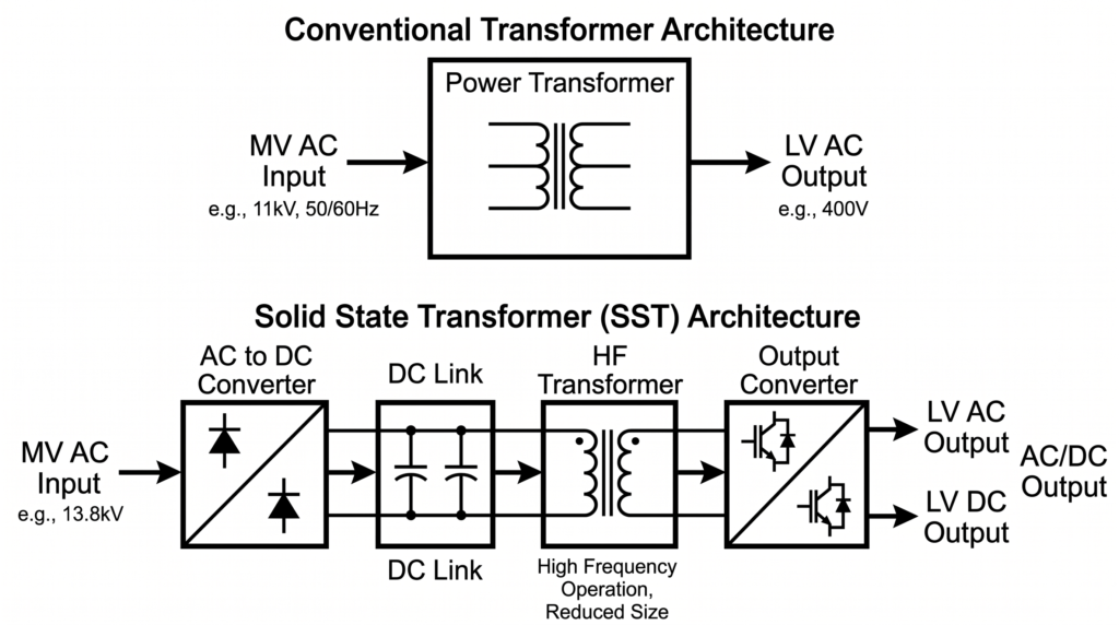
A Solid State Transformer (SST) is an electrically controlled transformer system that uses semiconductor power converters and a high-frequency transformer to transfer electrical energy between voltage levels.
A simplified conventional transformer can be represented as:
Medium Voltage AC → 50/60 Hz Transformer → Low Voltage AC
An SST typically follows a more sophisticated energy-conversion path:
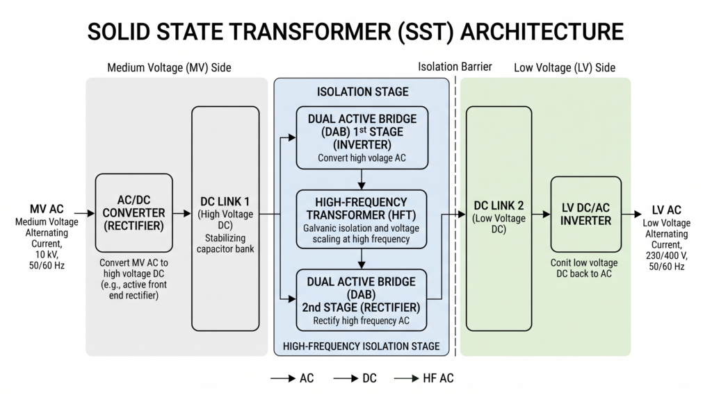
Medium Voltage AC → AC/DC Converter → DC Link
→ High-Frequency DC/DC Converter + Transformer
→ DC/AC or DC Output
Depending on its topology, an SST may contain several conversion stages. The high-frequency transformer provides galvanic isolation and voltage transformation, while semiconductor stages provide the controllability that differentiates an SST from a conventional distribution transformer.
Why Solid State Transformers Matter for Renewable Energy
Renewable energy systems have electrical characteristics that create new challenges for distribution networks.
Solar PV output varies with irradiance. Wind generation varies with wind speed. Battery systems operate in both charging and discharging modes. EV charging creates large controllable loads. Distribution feeders can experience reverse power flow when local renewable generation exceeds local consumption.
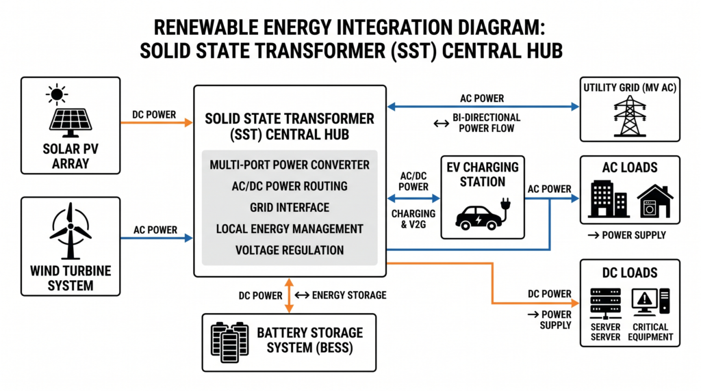
An SST can be designed to provide an electronic interface between these resources and the electrical grid.
Solar PV → DC Bus → SST → Medium-Voltage Grid

Grid → SST → DC Bus → Battery Storage

Grid → SST → AC Output → Local Loads
Basic Solid State Transformer Architecture
Stage 1: Medium-Voltage AC to DC
The incoming medium-voltage AC supply is connected to a controlled power-electronic converter. A simplified representation is:
MV AC → Multilevel Converter → DC Link
Examples include:
- Cascaded H-bridge converters
- Modular multilevel converters
- Neutral-point-clamped converters
- Active-front-end converters
The converter controls the current drawn from the grid, providing opportunities for power-factor correction, reactive-power control, harmonic reduction, active-power regulation, and bidirectional power flow.
Stage 2: High-Frequency DC/DC Conversion
The DC link feeds a high-frequency isolated DC/DC converter. A common concept is the Dual Active Bridge (DAB).
Conceptually:
DC → High-Frequency AC → Transformer → High-Frequency AC → DC
The transformer provides galvanic isolation and voltage transformation. Unlike a conventional 50/60 Hz transformer, this transformer operates at a much higher switching frequency.
Stage 3: Low-Voltage Output Conversion
The resulting DC voltage can either remain available as a DC distribution bus or be converted back into AC.
DC Link → Inverter → LV AC
DC Link → DC Output
This is particularly attractive because many modern electrical systems internally use DC power, including batteries, EV chargers, data centers, LED systems, and solar PV equipment.
Simplified SST Block Diagram
             MEDIUM-VOLTAGE GRID
                     │
                     ▼
          ┌─────────────────────┐
          │ MV AC/DC Converter  │
          │ Multilevel / AFE    │
          └──────────┬──────────┘
                     │
                     ▼
                MV DC LINK
                     │
                     ▼
          ┌─────────────────────┐
          │ High-Frequency      │
          │ DC/DC Converter     │
          │       +             │
          │ HF Transformer      │
          └──────────┬──────────┘
                     │
                     ▼
                LV DC LINK
              ┌──────┴──────┐
              │             │
              ▼             ▼
         DC Loads       DC/AC Inverter
                            │
                            ▼
                         AC Loads
Role of Wide-Bandgap Semiconductors
One technology supporting advanced SST development is the use of wide-bandgap semiconductor devices. The most important materials are silicon carbide (SiC) and gallium nitride (GaN).
For medium-voltage power conversion, SiC devices are particularly significant because they can operate at high voltage and high switching frequency with favorable switching characteristics.
Higher switching frequency can allow:
- Smaller magnetic components
- Higher power density
- Faster control response
- Reduced passive-component size
However, higher switching frequency is not automatically better. It can increase switching losses, electromagnetic interference, insulation stress, common-mode currents, and thermal-management requirements.
Solid State Transformers vs Conventional Transformers
| Characteristic | Conventional Transformer | Solid-State Transformer |
|---|---|---|
| Voltage transformation | Yes | Yes |
| 50/60 Hz operation | Normally | Not necessarily |
| High-frequency transformer | No | Yes |
| Power-electronic switches | No | Yes |
| Bidirectional operation | Not inherent | Designed into topology |
| Active voltage regulation | Limited | Strong capability |
| Reactive-power control | No direct control | Possible |
| Harmonic compensation | Passive/system dependent | Can be actively controlled |
| DC output | No | Yes |
| Power-flow control | Limited | High |
| Power density | Moderate | Potentially high |
| Control complexity | Low | High |
| Cooling complexity | Moderate | High |
Major Benefits of Solid State Transformers in Renewable Energy
Bidirectional Power Flow
Renewable energy networks increasingly require power to flow in both directions. For example:
- PV → Grid during high solar production
- Grid → Battery during charging
- Battery → Grid during discharge
Voltage Regulation
An SST can regulate voltage electronically. This can help compensate for PV voltage rise, feeder voltage variations, rapid load changes, and reverse power flow.
Reactive Power Control
An SST can exchange reactive power with the grid when its converter topology and control system are designed for this function. This can support voltage regulation, power-factor correction, and reduced reactive current.
Integration of Battery Storage
Battery energy storage systems operate naturally on DC. An SST can provide a direct controlled DC interface, potentially reducing unnecessary conversion stages depending on the system architecture.
DC Distribution
Many renewable-energy technologies are inherently DC, including solar PV modules, batteries, fuel cells, electrolyzers, EV batteries, and many electronic loads. An SST can provide a DC bus while interfacing with an AC distribution network.
Applications of Solid State Transformers
Solar PV Plants
An SST can potentially coordinate PV generation, grid voltage, reactive power, battery storage, DC collection, curtailment, and grid-support functions.
Wind Energy
An SST can serve as a controllable interface between wind generation and the distribution network, supporting voltage regulation, reactive-power management, power-flow control, and medium-voltage conversion.
Battery Energy Storage Systems
Battery storage is one of the natural applications for SST technology because the battery is inherently a DC source/sink.
EV Charging Infrastructure
An SST can potentially combine several conversion functions in a medium-voltage EV charging station:
MV AC → SST → DC Bus → Multiple EV Chargers
Renewable Energy Microgrids
An SST can operate as a controllable electrical gateway between a microgrid and utility grid, coordinating solar, wind, battery storage, EVs, and loads.
Engineering Example: Solar PV + Battery + SST
Given:
- Solar PV = 1 MW
- Battery = 500 kW
- Grid voltage = 13.8 kV, three-phase
- Local DC bus = 1,000 V DC
- LV AC loads = 480 V, three-phase
The system could be represented as:
                 13.8 kV GRID
                     │
                     ▼
             ┌───────────────┐
             │ MV SST Stage  │
             └───────┬───────┘
                     │
                  DC LINK
              ┌──────┼───────┐
              │      │       │
              ▼      ▼       ▼
             PV    Battery  DC Loads
              │      │
              └──────┤
                     │
                     ▼
              DC/AC INVERTER
                     │
                     ▼
                 480 V AC
                     │
                     ▼
                 AC Loads
For 1 MW export at 13.8 kV and unity power factor, the idealized three-phase line current is:
Three-phase line currentI =P√3 × V
Substituting the values:
I =1,000,000 W√3 × 13,800 V≈ 41.8 A
Result: the idealized grid-side current is approximately 41.8 A.
Engineering note: actual SST input current must account for converter losses, power factor, harmonics, control strategy, and operating conditions.
Engineering Example: Voltage Regulation
Consider a feeder with a nominal LV voltage of 400 V. During heavy PV production, the feeder voltage rises to 420 V.
Voltage deviationΔV =Vactual − VnominalVnominal× 100%
Substituting:
ΔV =420 − 400400× 100% = 5%
Result: the feeder voltage is approximately 5% above nominal.
A suitably designed SST can respond electronically to regulate downstream voltage. The permissible voltage range and response requirements depend on the applicable grid code and interconnection requirements.
Power Losses and Efficiency
SST efficiency is determined by multiple components:
Total power lossesPloss= Pswitching+ Pconduction+ Pmagnetic+ Pcapacitor+ Pthermal+ Pcontrol
Efficiencyη =PoutPin× 100%
For example, if the input power is 1,010 kW and output power is 1,000 kW:
Ploss= 1,010 − 1,000 =10 kW
η =1,0001,010× 100% ≈99.0%
This is an illustrative calculation, not a universal SST efficiency value. Engineers should evaluate efficiency across the complete operating profile, particularly at partial load.
Thermal Management
Thermal design is one of the most important engineering challenges in Solid-State Transformers. Heat sources include semiconductor conduction losses, switching losses, transformer core and winding losses, capacitor losses, busbar losses, and auxiliary power consumption.
Possible cooling approaches include forced air, liquid cooling, heat sinks, cold plates, direct semiconductor cooling, and hybrid systems.
Simplified junction-temperature relationshipTj= Ta+ Ploss× RθJA
Where:
- Tj = semiconductor junction temperature
- Ta = ambient temperature
- Ploss = semiconductor losses
- RθJA = junction-to-ambient thermal resistance
High-power SST systems normally require a complete thermal model rather than relying on a single lumped calculation.
Harmonics and Power Quality
Because SSTs use power electronics, harmonic behavior must be considered carefully. A well-designed converter can reduce low-frequency harmonic current through PWM control, multilevel topologies, active filtering, and appropriate modulation strategies.
At the same time, switching converters generate high-frequency components. A complete power-quality study should therefore consider both low-order grid harmonics and high-frequency switching emissions.
Protection Challenges
Protection is fundamentally different from protection of a conventional transformer. Power semiconductors may have much shorter fault-withstand times than traditional transformer components.
An SST may require coordinated protection involving:
- Fast semiconductor protection
- DC-link protection
- AC-side circuit breakers
- Fuses where appropriate
- Overvoltage protection
- Overcurrent protection
- Device-fault detection
- Ground-fault detection
- Thermal protection
- Isolation monitoring
- Control-system interlocks
Grounding and Isolation
The presence of multiple AC and DC voltage domains makes grounding more complicated. Engineers must determine where the neutral is established, whether the DC bus is floating or referenced, how galvanic isolation is implemented, how ground faults are detected, and how protective bonding is performed.
Grounding must be designed for the complete SST system rather than copied directly from a conventional transformer installation.
Standards and Codes Relevant to SST Projects
IEC
IEC 62477-1 is relevant to the safety of power-electronic converter systems. IEC 60076 is the major family of standards for power transformers and may be relevant to the transformer portion of an SST depending on its construction and application.
IEEE
IEEE 1547 is important where an SST interfaces distributed energy resources with an electric power system. IEEE 519 is relevant to harmonic-control objectives and power quality at the point of common coupling.
NEC
For U.S. installations, the National Electrical Code (NFPA 70) must be evaluated according to the specific installation. Depending on the project, relevant provisions can include Articles 690, 691, 694, 705, 706, 250, and 240.
Important: Always verify the code edition adopted by the authority having jurisdiction (AHJ), applicable utility requirements, manufacturer instructions, and project-specific standards before design or installation.
SST vs Conventional Transformer: Practical Decision Matrix
| Design Requirement | Conventional Transformer | SST |
|---|---|---|
| Basic voltage conversion | Excellent | Excellent |
| Simple distribution | Excellent | Often unnecessary |
| Low initial complexity | Excellent | Poorer |
| Bidirectional power flow | Limited | Excellent |
| Renewable integration | Good | Excellent |
| Battery integration | External converter normally required | Strong capability |
| DC distribution | No | Yes |
| Dynamic voltage control | Limited | Excellent |
| Reactive power control | External equipment | Potentially integrated |
| High-speed control | No | Yes |
| Maintenance simplicity | Excellent | Moderate |
| Power-electronics expertise | Low | High |
Common SST Design Mistakes
1. Treating an SST Like a Conventional Transformer
An SST is a power-electronic system. Designers must consider switching frequency, control loops, semiconductor losses, EMI, thermal cycling, DC-link behavior, and converter stability.
2. Looking Only at Peak Efficiency
Peak efficiency can be misleading. A renewable-energy installation may spend significant time at partial load. A weighted efficiency profile is more useful for system-level evaluation.
3. Ignoring DC Faults
DC faults are challenging because conventional AC current zero crossings are absent. Protection must be specifically designed for DC fault interruption and stored-energy discharge.
4. Underestimating Thermal Cycling
Variable renewable generation can create repeated thermal cycles affecting semiconductor packaging, solder joints, capacitors, transformer insulation, and busbars.
5. Ignoring Control Interaction
An SST may interact with PV inverters, battery inverters, EV chargers, grid-forming converters, grid-following converters, protection relays, and utility voltage regulators. Control-loop interaction should be evaluated during system studies.
Safety Considerations
Electrical Safety
- Open the appropriate AC disconnects.
- Isolate DC sources.
- Disable renewable-energy inputs.
- Disconnect battery systems where applicable.
- Wait for the manufacturer’s specified DC-link discharge time.
- Verify absence of voltage using properly rated test equipment.
- Apply lockout/tagout procedures.
- Establish protective grounding where required.
- Follow the manufacturer’s maintenance procedure.
A DC link can remain energized after the AC supply has been disconnected.
Arc-Flash Safety
Arc-flash risk must be assessed using applicable workplace and electrical-safety requirements. Stored energy in DC-link capacitors, batteries, PV arrays, and distribution feeders must be considered.
Thermal Safety
Cooling-system failures can cause semiconductor overheating. Monitoring should include heat-sink temperature, coolant temperature, thermal estimates, fan/pump status, cabinet temperature, and transformer temperature.
Practical SST Commissioning Procedure
Step 1 — Visual Inspection
Check enclosure condition, busbars, cable terminations, grounding conductors, cooling systems, labels, and mechanical fasteners.
Step 2 — Insulation Testing
Perform the manufacturer’s specified insulation and dielectric tests. Do not apply test voltages blindly to semiconductor circuits.
Step 3 — Control-System Verification
Check firmware, protection settings, control parameters, communications, interlocks, and emergency-stop functions.
Step 4 — Energization Without Load
Verify DC-link voltage, input current, output voltage, temperatures, abnormal noise, and fault indications.
Step 5 — Controlled Load Testing
Increase load gradually while monitoring efficiency, harmonics, temperature, voltage regulation, current balance, and power factor.
Step 6 — Renewable-Energy Testing
Test PV ramping, battery charging, battery discharging, reverse power flow, reactive-power control, and grid-loss response.
Step 7 — Protection Testing
Verify protection functions under controlled test conditions.
Where Solid State Transformers Make the Most Sense
- Renewable-energy microgrids
- EV charging hubs
- Data centers
- Industrial microgrids
- Distribution-grid modernization
- Hybrid AC/DC systems
- Battery-integrated renewable installations
Advantages and Disadvantages
Advantages
- Bidirectional power flow
- Fast voltage regulation
- Reactive-power control
- Potential power-factor correction
- Renewable-energy integration
- Battery integration
- DC output capability
- High power-density potential
- Advanced monitoring
- Grid-support capabilities
Disadvantages
- Higher control complexity
- More semiconductor devices
- Greater cooling requirements
- More sophisticated protection
- EMI considerations
- Complex maintenance
- Higher engineering requirements
- Semiconductor lifetime considerations
- Dependence on control software
- Higher cost in some applications
Future of Solid State Transformers in Renewable Energy
The future development of SSTs is closely connected to wide-bandgap power devices, modular architectures, DC microgrids, grid-forming operation, digital monitoring, predictive maintenance, and energy-management systems.
The SST could increasingly operate as an intelligent energy gateway that continuously coordinates:
Generation + Storage + Loads + Grid
Frequently Asked Questions
1. What is a Solid State Transformer?
A Solid-State Transformer is a transformer-based power-conversion system that uses semiconductor converters and a high-frequency transformer to provide voltage conversion, isolation, and advanced electrical control.
2. How does a Solid State Transformer work with solar energy?
An SST can connect solar PV to a DC bus or AC grid through controlled power-electronic stages. Depending on its architecture, it can also coordinate battery storage, loads, and grid power exchange.
3. Are Solid State Transformers more efficient than conventional transformers?
Not necessarily in every operating condition. Conventional transformers are extremely efficient and mature. SSTs can provide additional system-level benefits through power conversion and control, but semiconductor and auxiliary losses must be evaluated across the complete operating profile.
4. Can an SST provide bidirectional power flow?
Yes. Many SST topologies are designed for bidirectional power transfer, making them suitable for batteries, renewable generation, and microgrids.
5. Can Solid State Transformers replace conventional transformers?
They can replace conventional transformers in some applications, but not universally. The decision depends on cost, power rating, reliability, protection, control requirements, grid code, maintenance capability, and the value of additional power-electronic functions.
6. Do SSTs provide galvanic isolation?
Many SST architectures provide galvanic isolation through a high-frequency transformer. Isolation must be verified from the actual topology and manufacturer’s design.
7. What semiconductors are used in Solid-State Transformers?
Depending on voltage and power rating, SSTs can use IGBTs, MOSFETs, SiC MOSFETs, SiC diodes, and other semiconductor devices. Wide-bandgap SiC devices are particularly attractive for medium- and high-voltage applications.
8. What standards apply to Solid-State Transformers?
The applicable standards depend on the system and jurisdiction. IEC 62477-1 is highly relevant to power-electronic converter safety; IEC 60076 covers conventional power-transformer requirements where applicable; IEEE 1547 is important for DER interconnection; IEEE 519 addresses harmonic performance; and U.S. installations may involve NEC Articles 690, 691, 694, 705, and 706.
Conclusion
Solid State Transformers represent a major evolution in transformer technology because they combine voltage transformation with active power conversion and digital control.
For renewable-energy systems, this distinction is especially important. Solar PV, wind generation, battery storage, EV charging, and microgrids require electrical infrastructure capable of handling bidirectional power flows, rapidly changing operating conditions, and sophisticated grid-support requirements.
A conventional transformer performs its core function extremely well, but it is fundamentally a passive electromagnetic device. An SST can potentially act as an active energy gateway.
At the same time, SST technology introduces new engineering challenges. Designers must address semiconductor losses, thermal management, high-frequency transformer design, EMI, DC faults, control stability, protection coordination, grounding, insulation coordination, and cybersecurity where networked controls are involved.
The most important engineering lesson is simple: an SST should not be selected merely because it is technologically advanced. It should be selected when its controllability and system-level functionality create enough technical or economic value to justify its additional complexity.
Int