
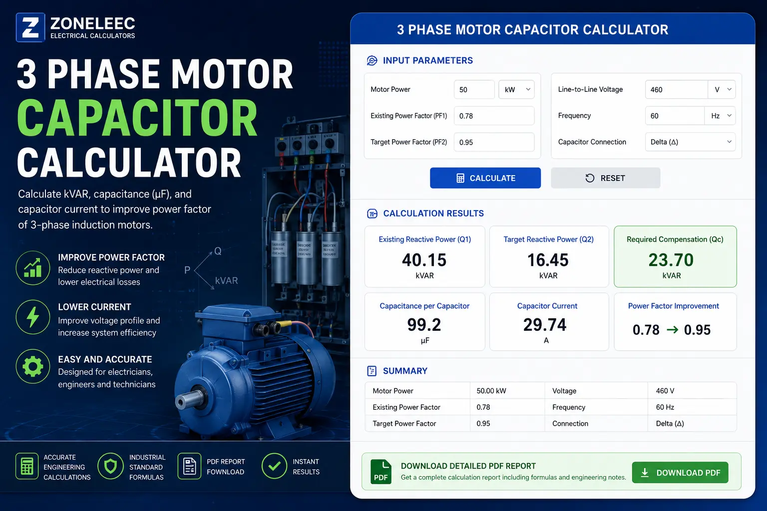
3 Phase Motor Capacitor Calculator
A 3 phase motor capacitor calculator helps determine the amount of reactive power compensation required to improve the power factor of a three-phase induction motor.
By entering the motor’s active power, existing power factor, target power factor, line voltage, frequency, and capacitor connection, you can calculate:
- Existing reactive power
- Target reactive power
- Required capacitor compensation in kVAR
- Capacitor capacitance in µF
- Capacitor current
- Required capacitance per capacitor
The calculator is useful for electricians, electrical engineers, technicians, maintenance personnel, students, and industrial professionals working with three-phase motors and power-factor correction systems.
Important: The calculated capacitance is a theoretical value. Final capacitor selection must consider motor loading, harmonics, resonance, capacitor voltage rating, switching conditions, temperature, protection, and the manufacturer’s specifications.
1. 3 Phase Motor Capacitor Calculator
3 Phase Motor Capacitor Calculator
Calculate required power factor correction, capacitor kVAR, capacitance in µF, and capacitor current.
Motor & Electrical Parameters
Calculation Results
Step-by-Step Calculation
| Parameter | Result |
|---|---|
| Motor Power | — |
| Existing Power Factor | — |
| Target Power Factor | — |
| Line Voltage | — |
| Frequency | — |
| Capacitor Connection | — |
| Required Compensation | — |
| Capacitance | — |
| Capacitor Current | — |
Download Engineering Report
Generate a PDF report containing the input parameters, calculated results, formulas, and engineering safety notes.
2. What Is Capacitor Sizing?
Capacitor sizing is the process of determining the appropriate capacitance or reactive-power rating required to improve the power factor of an electrical load.
Three-phase induction motors are inherently inductive loads. Their magnetic fields require reactive power to establish the motor's magnetic flux.
The motor therefore draws two major components of power:
- Active power (kW) — performs useful mechanical work.
- Reactive power (kVAR) — supports the magnetic field.
- Apparent power (kVA) — combination of active and reactive power.
The relationship can be represented as:
S² = P² + Q²
Where:
- S = apparent power in kVA
- P = active power in kW
- Q = reactive power in kVAR
A low power factor means that more apparent power and current are required to deliver the same useful active power.
Adding a properly sized capacitor supplies part of the required reactive power locally.
As a result:
Motor → draws less reactive power from the supply
Supply → delivers less current for the same active power
This can improve:
- Power factor
- Voltage profile
- Transformer utilization
- Feeder capacity
- Electrical losses
- Overall system efficiency
However, a capacitor does not increase the motor's mechanical output power.
3. Three-Phase Motor Capacitor Formula
The fundamental formula for power-factor correction is:
Qc = P × [tan(φ₁) − tan(φ₂)]
Where:
- Qc = required capacitor compensation in kVAR
- P = active power in kW
- φ₁ = angle corresponding to the existing power factor
- φ₂ = angle corresponding to the target power factor
The angles are calculated using:
φ₁ = cos⁻¹(PF₁)
φ₂ = cos⁻¹(PF₂)
Therefore, the complete calculation can be written as:
Qc = P × [tan(cos⁻¹(PF₁)) − tan(cos⁻¹(PF₂))]
This is the main equation used by the Zoneleec calculator.
3.1 Existing Reactive Power
The existing reactive power is:
Q₁ = P × tan(φ₁)
For example, if:
- P = 50 kW
- PF₁ = 0.78
First calculate the angle:
φ₁ = cos⁻¹(0.78)
φ₁ ≈ 38.74°
Then:
tan(38.74°) ≈ 0.803
Therefore:
Q₁ = 50 × 0.803
Q₁ ≈ 40.15 kVAR
3.2 Target Reactive Power
Suppose the target power factor is 0.95.
First:
φ₂ = cos⁻¹(0.95)
φ₂ ≈ 18.19°
Then:
tan(18.19°) ≈ 0.329
Therefore:
Q₂ = 50 × 0.329
Q₂ ≈ 16.45 kVAR
3.3 Required Capacitor kVAR
Now subtract the target reactive power from the existing reactive power:
Qc = Q₁ − Q₂
Substituting the values:
Qc = 40.15 − 16.45
Qc ≈ 23.70 kVAR
Therefore:
Required capacitor compensation = 23.70 kVAR
This is much clearer than presenting the formula as an unexplained mathematical expression.
4. Capacitance Calculation
Once the required capacitor rating in kVAR is known, the capacitance can be calculated.
The formula depends on whether the three capacitor elements are connected in Delta or Star.
Delta Connection
For a delta-connected capacitor bank:
Qc = 3 × 2πfCV²
Rearranging:
C = Qc / (3 × 2πfV²)
Where:
- C = capacitance of each capacitor in farads
- Qc = total capacitor reactive power in VAR
- f = frequency in Hz
- V = line-to-line voltage in volts
To convert farads to microfarads:
C(µF) = C(F) × 1,000,000
Star Connection
For a star-connected capacitor bank:
Qc = 2πfCV²
Therefore:
C = Qc / (2πfV²)
The important difference is that the voltage across each capacitor is different between Delta and Star connections.
This is why the calculator must know the capacitor connection before calculating the capacitance.
6. Capacitor Current
The capacitor current can also be estimated from the reactive power:
Ic = Qc / (√3 × V)
For the example:
Ic = 23,700 / (√3 × 460)
Therefore:
Ic ≈ 29.74 A
This value is useful when evaluating:
- Capacitor switching equipment
- Contactors
- Protection
- Conductors
- Disconnects
- Busbars
- Capacitor-bank components
7. Capacitor Selection Table
The following table can be used as a general engineering reference.
| Required Compensation | Typical Application |
|---|---|
| 1–5 kVAR | Small motors |
| 5–15 kVAR | Small/medium industrial motors |
| 15–30 kVAR | Medium industrial motors |
| 30–50 kVAR | Larger motors |
| 50–100 kVAR | Large industrial loads |
| 100+ kVAR | Large capacitor banks / centralized correction |
These are application ranges, not universal motor sizing rules.
The actual capacitor rating should be calculated from the motor operating conditions and then matched to available manufacturer ratings.
8. Individual Motor Capacitor vs Capacitor Bank
There are two common approaches to power-factor correction.
Individual Motor Correction
A capacitor is installed directly at or near the motor.
Advantages
- Reactive power is supplied close to the load.
- Reduces reactive current in upstream conductors.
- Useful for large motors operating for long periods.
- Can reduce demand on upstream electrical equipment.
Disadvantages
- Capacitor must be correctly coordinated with the motor.
- Switching and isolation arrangements require careful design.
- Incorrect sizing can cause overcorrection.
Centralized Capacitor Bank
A capacitor bank is installed at the main distribution board or switchboard.
Advantages
- Easier centralized control.
- Automatic capacitor steps can follow changing loads.
- Suitable for facilities with many motors.
- Easier to maintain in some installations.
Disadvantages
- Reactive current may still flow through individual motor feeders.
- Harmonic resonance must be considered.
- Requires appropriate capacitor-bank control and protection.
For facilities with highly variable loads, an automatic power factor correction (APFC) system may be more appropriate than fixed capacitors.
9. Single-Phase vs Three-Phase Motor Capacitors
Single-phase and three-phase motors should not be treated as identical capacitor-sizing problems.
| Feature | Single Phase | Three Phase |
|---|---|---|
| Supply | Single-phase | Three-phase |
| Typical capacitor use | Starting/running circuits | Power-factor correction |
| Phase arrangement | One phase | Three phases |
| Common capacitor connection | Motor-specific | Delta or Star |
| Main calculation | Motor design dependent | kVAR/PF correction |
| Typical application | Small motors | Industrial motors |
| Starting capacitor | Common | Generally not used in the same way |
A starting capacitor is fundamentally different from a capacitor used for power-factor correction.
Do not use the power-factor correction formula to select a motor starting capacitor.
For starting-capacitor calculations, link to:
[Starting Capacitor Calculator]
10. What Is the Difference Between a Starting Capacitor and a Power-Factor Capacitor?
This distinction is important.
Starting Capacitor
A starting capacitor is used primarily to create the necessary phase shift and starting torque in certain motor designs.
It is generally associated with single-phase motors.
The capacitor is often switched out of the circuit after the motor accelerates.
Power-Factor Correction Capacitor
A power-factor correction capacitor supplies leading reactive power to offset the lagging reactive power of inductive loads.
It is commonly used with:
- Three-phase induction motors
- Transformers
- Industrial distribution systems
- Motor control centers
- Manufacturing facilities
Therefore:
Starting capacitor ≠ power-factor correction capacitor
11. Common Mistakes When Sizing a 3 Phase Motor Capacitor
Mistake 1 — Using Motor HP Directly as kW
HP and kW are not identical.
The basic conversion is:
1 HP ≈ 0.746 kW
But motor nameplate HP represents mechanical output, while power-factor calculations require electrical active input power.
Motor efficiency should therefore be considered when converting mechanical motor output into electrical input power.
Mistake 2 — Ignoring Motor Loading
A motor does not necessarily operate continuously at its rated load.
Power factor changes with loading.
A capacitor correctly sized for full-load operation may produce excessive correction when the motor operates lightly loaded.
Mistake 3 — Correcting the Power Factor to Exactly 1.00
Trying to force the power factor to unity is often unnecessary and can create overcorrection problems.
A practical target might be around:
0.90–0.98
depending on the installation.
The appropriate target should be based on the utility requirements, operating profile, and engineering design.
Mistake 4 — Ignoring Harmonics
Modern industrial installations may contain:
- Variable-frequency drives
- UPS systems
- Rectifiers
- Switching power supplies
- LED drivers
- Welders
- Power electronic converters
Capacitors can interact with system inductance and create resonance.
A harmonic study may therefore be required before installing substantial capacitor banks.
Mistake 5 — Using the Wrong Voltage
For a three-phase Delta capacitor calculation, the formula uses the line-to-line voltage across each capacitor.
Using phase voltage instead can produce a significantly incorrect capacitance value.
Mistake 6 — Forgetting Frequency
Capacitive reactance depends on frequency.
Therefore, the same capacitor does not provide the same reactive power at 50 Hz and 60 Hz.
For a fixed capacitance:
Qc ∝ f
So frequency must be included in the calculation.
12. Safety Considerations
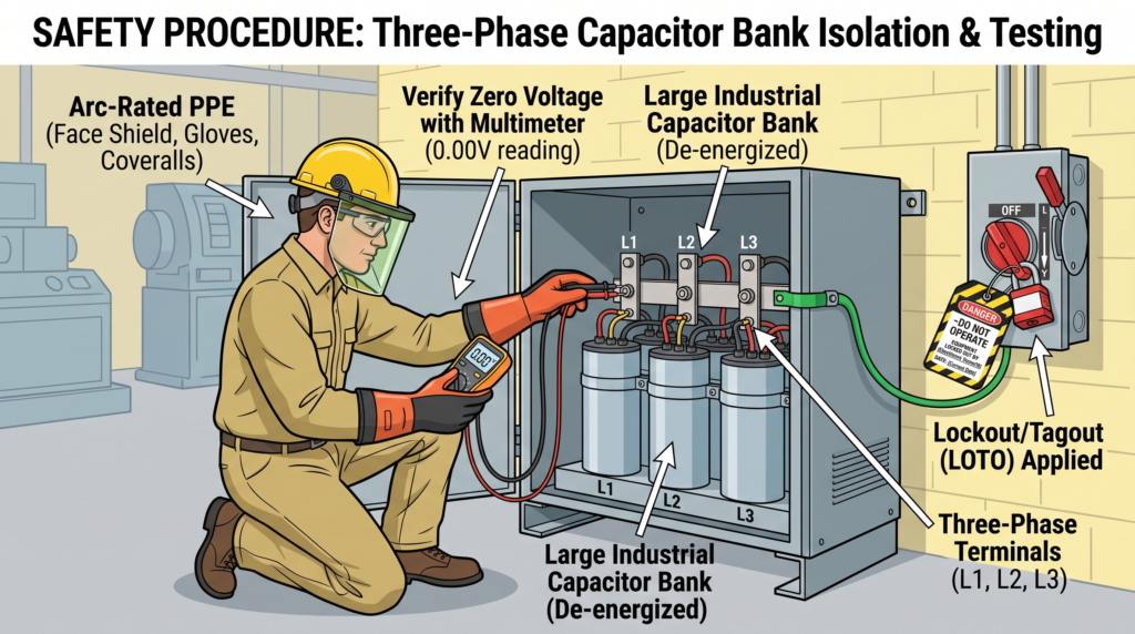
Power-factor correction capacitors store electrical energy.
Even after the supply has been disconnected, dangerous voltage may remain across the capacitor terminals if the discharge system is defective or insufficient.
Before working on capacitor equipment:
- Disconnect the supply.
- Apply lockout/tagout procedures.
- Verify isolation.
- Wait for the manufacturer's specified discharge time.
- Test for absence of voltage.
- Follow the manufacturer's discharge procedure.
- Use appropriate PPE.
- Inspect the capacitor and associated equipment for damage.
- Verify correct capacitor voltage rating.
- Confirm that protection and switching equipment are correctly rated.
For industrial installations, the design should also consider:
- Short-circuit protection
- Overcurrent protection
- Capacitor switching
- Discharge resistors
- Harmonics
- Resonance
- Temperature
- Ventilation
- Enclosure requirements
- Earthing/bonding
- Maintenance procedures
Always follow applicable local electrical regulations and the equipment manufacturer's instructions.
13. NEC, IEC and IEEE Considerations
The exact requirements depend on the installation jurisdiction and equipment type.
For US installations, relevant requirements can include the National Electrical Code (NEC), particularly provisions dealing with capacitors, conductors, overcurrent protection, disconnecting means, and motor installations.
For international installations, relevant IEC standards may include:
- IEC 60252-1 — AC motor capacitors
- IEC 60831-1 — Low-voltage shunt power capacitors
- IEC 61921 — Low-voltage power factor correction capacitor banks
For capacitor application and performance considerations, IEEE 18 is also an important reference for shunt power capacitors.
Standards should always be checked against the current edition applicable to your installation.
14. When Should You Use a 3 Phase Motor Capacitor Calculator?
A calculator is particularly useful during:
Electrical design
Estimate the required reactive compensation during preliminary system design.
Maintenance
Investigate poor power factor and determine an initial capacitor requirement.
Industrial upgrades
Estimate the size of a capacitor bank required after adding motors or other inductive loads.
Energy audits
Evaluate potential power-factor correction requirements.
Training
Students and technicians can use the calculation to understand the relationship between:
kW → PF → kVAR → capacitance
15. Practical Engineering Workflow
For a real installation, don't simply calculate a capacitor and immediately connect it.
Use this workflow:
Step 1 — Measure the motor
Determine:
- Voltage
- Current
- Active power
- Power factor
- Operating load
- Operating hours
Step 2 — Determine the required PF
Establish the desired target based on:
- Utility requirements
- Plant operating conditions
- Electrical design
- Economic considerations
Step 3 — Calculate kVAR
Use:
Qc = P × [tan(φ₁) − tan(φ₂)]
Step 4 — Select capacitor configuration
Determine whether the capacitor system is:
- Delta
- Star
- Fixed
- Automatic stepped
Step 5 — Check harmonics
If nonlinear loads are significant, investigate resonance and harmonic distortion.
Step 6 — Select equipment
Select:
- Capacitors
- Contactors
- Fuses/breakers
- Disconnects
- Conductors
- Protection
- Controllers
Step 7 — Verify operation
After installation, measure:
- Voltage
- Current
- PF
- kVAR
- Harmonic distortion
- Capacitor temperature
16. Common Questions About Three-Phase Motor Capacitors
FAQ 1: How do I calculate a capacitor for a 3 phase motor?
Calculate the required reactive compensation using:
Qc = P × [tan(φ₁) − tan(φ₂)]
Then convert the required kVAR into capacitance using the appropriate Delta or Star capacitor equation.
FAQ 2: How many µF does a 3 phase motor need?
There is no single µF value for all three-phase motors.
The required capacitance depends on:
- Motor power
- Existing PF
- Target PF
- Voltage
- Frequency
- Capacitor connection
Use the Zoneleec calculator to determine the theoretical capacitance.
FAQ 3: Can I connect a capacitor directly to a three-phase motor?
A capacitor can be connected for power-factor correction in appropriate applications, but the installation must be correctly designed.
Motor operating conditions, switching arrangements, protection, harmonics, resonance, and manufacturer recommendations must be considered.
FAQ 4: Is Delta or Star better for a three-phase capacitor?
Neither is universally better.
The required capacitance per capacitor differs because the voltage across each capacitor differs between Delta and Star.
The connection should be selected based on the capacitor equipment, voltage rating, system design, and manufacturer requirements.
FAQ 5: What capacitor size do I need for a 50 kW motor?
It depends on the initial and target power factors.
For example, at:
- 50 kW
- PF = 0.78
- Target PF = 0.95
the theoretical compensation is approximately:
23.7 kVAR
At 460 V, 60 Hz, Delta connection, this corresponds to approximately:
99.2 µF per capacitor
FAQ 6: Does a capacitor reduce motor power consumption?
A power-factor correction capacitor does not directly reduce the motor's mechanical energy requirement.
It reduces the reactive power supplied by the upstream electrical system and can reduce current and associated distribution losses.
Actual energy savings depend on the installation and operating conditions.
FAQ 7: Can capacitor banks cause harmonics?
Yes.
Capacitors can interact with the inductance of transformers and distribution networks and potentially create resonant conditions.
Installations containing significant nonlinear loads should be evaluated for harmonic distortion and resonance before capacitor-bank installation.
FAQ 8: Should I correct the motor power factor to 1.0?
Not necessarily.
Overcorrection can cause leading power factor and other undesirable operating conditions.
A practical target is normally selected below unity and based on the actual installation requirements.
17. Related Zoneleec Calculators
If you're working with motors and electrical power systems, these calculators can be used together.
Starting Capacitor Calculator
Use this when you need to estimate the requirements of a motor starting capacitor, particularly for single-phase motor applications.
Power Factor Correction Calculator
Use this calculator to determine the reactive compensation required to improve the power factor of an electrical load or installation.