
Distribution Transformer Explained: Types, Working Principle, Losses & Protection
Introduction
A Distribution Transformer is one of the most critical components in modern electrical power systems. Whether supplying electricity to residential neighborhoods, commercial facilities, industrial plants, or renewable energy systems, distribution transformers ensure safe and efficient voltage conversion for end users.
From utility substations to factory floors, distribution transformers play a vital role in delivering reliable electrical energy while minimizing transmission losses and maintaining voltage stability. Despite their widespread use, many technicians and engineering students only understand the basic concept of transformers without fully grasping their operational principles, loss mechanisms, protection systems, and efficiency considerations.
This comprehensive guide explains everything professionals need to know about distribution transformers, including:
- Working principles
- Transformer construction
- Types of distribution transformers
- Transformer losses
- Transformer efficiency
- Cooling systems
- Protection methods
- NEC, IEC, and IEEE standards
- Practical engineering applications
- Common installation mistakes
- Maintenance best practices
Whether you are an electrician, electrical engineer, maintenance technician, or engineering student, this article will provide both theoretical understanding and practical field knowledge.
What Is a Distribution Transformer?
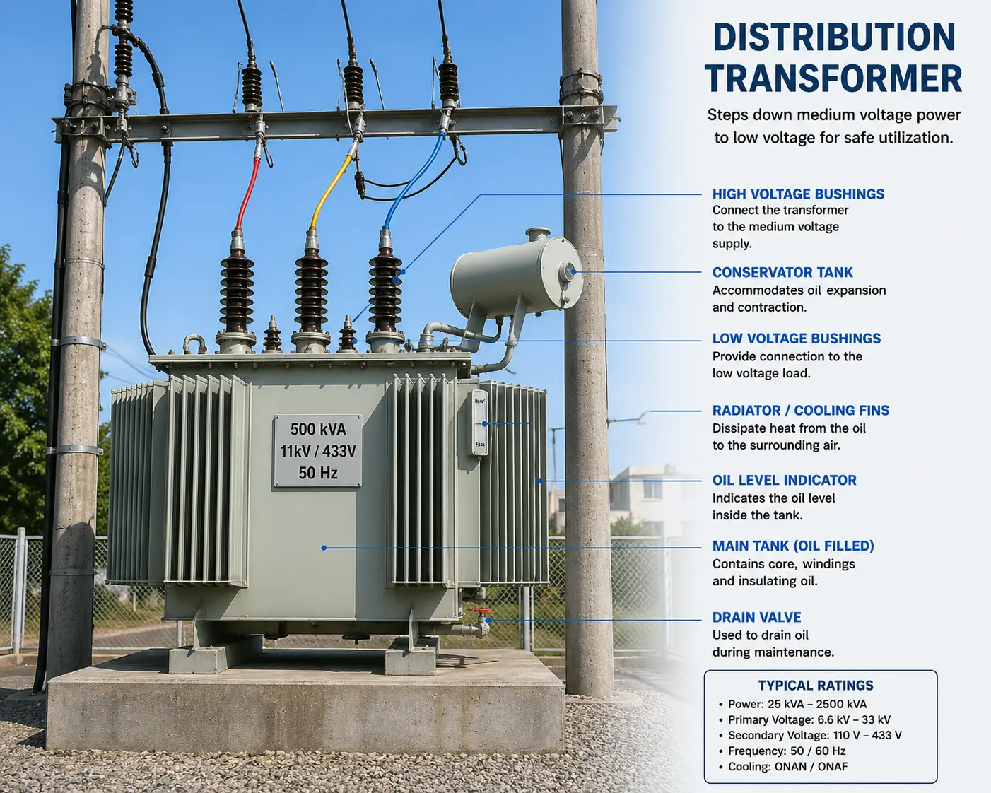
A Distribution Transformer is a static electrical device used to step down medium-voltage electrical power to lower utilization voltages suitable for residential, commercial, and industrial loads.
Typically, distribution transformers reduce voltage from:
| Primary Voltage | Secondary Voltage |
|---|---|
| 11 kV | 415/240 V |
| 13.8 kV | 480/277 V |
| 33 kV | 400/230 V |
Distribution transformers operate continuously under varying load conditions and are designed for maximum efficiency at partial load rather than full load.
They are generally installed:
- On utility poles
- In pad-mounted enclosures
- Inside substations
- In industrial power distribution systems
- In renewable energy plants
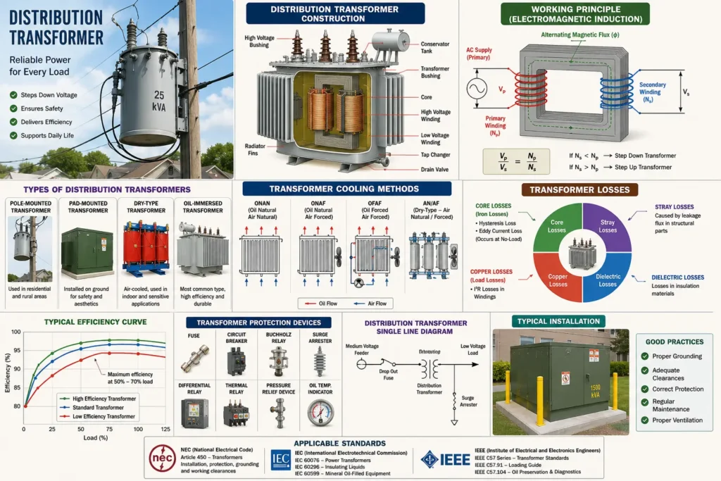
Working Principle of a Distribution Transformer
Electromagnetic Induction Principle
Table of Contents
Main Components of a Distribution Transformer
1. Transformer Core
The core provides a low-reluctance path for magnetic flux.
Common Core Materials
- Silicon steel laminations
- CRGO steel (Cold Rolled Grain Oriented steel)
- Amorphous metal cores
Core Types
- Core-type transformer
- Shell-type transformer
Amorphous metal cores are increasingly used because they significantly reduce no-load losses.
2. Windings
Transformers contain:
- Primary winding
- Secondary winding
Materials used:
- Copper conductors
- Aluminum conductors
Copper offers:
- Lower resistance
- Better thermal performance
- Higher efficiency
Aluminum is lighter and more economical.
3. Insulation System
Transformer insulation prevents electrical breakdown between windings and grounded components.
Common Insulation Materials
- Kraft paper
- Pressboard
- Transformer oil
- Epoxy resin
Insulation aging is one of the leading causes of transformer failure.
4. Transformer Oil
Oil serves two functions:
- Cooling
- Electrical insulation
Types of Transformer Oil
| Oil Type | Advantages |
|---|---|
| Mineral oil | Economical and widely used |
| Silicone oil | High fire resistance |
| Natural ester oil | Biodegradable and environmentally friendly |
5. Conservator Tank
The conservator accommodates oil expansion and contraction due to temperature changes.
6. Breather
The breather prevents moisture from entering the transformer tank.
Silica gel inside the breather absorbs humidity from incoming air.
7. Tap Changer
Tap changers regulate output voltage.
Types
- Off-load tap changer
- On-load tap changer (OLTC)
Types of Distribution Transformers
1. Pole-Mounted Distribution Transformer
Installed on utility poles for residential distribution networks.
Advantages
- Cost-effective
- Easy installation
- Suitable for rural areas
Limitations
- Limited power rating
- Exposed to weather conditions
2. Pad-Mounted Transformer
Installed at ground level inside locked metal enclosures.
Applications
- Urban distribution
- Commercial facilities
- Residential complexes
Advantages
- Improved safety
- Better aesthetics
- Lower visual pollution
3. Dry-Type Distribution Transformer
Uses air instead of oil for cooling.
Cooling Methods
- AN (Air Natural)
- AF (Air Forced)
Advantages
- Reduced fire risk
- Environmentally safer
- Lower maintenance
Applications
- Hospitals
- Data centers
- Commercial buildings
- Indoor installations
4. Oil-Immersed Distribution Transformer
The most common transformer type worldwide.
Advantages
- Better heat dissipation
- Higher overload capability
- Longer lifespan
Applications
- Utilities
- Industrial plants
- Outdoor substations
5. Hermetically Sealed Transformer
Completely sealed against atmospheric contamination.
Benefits
- Minimal moisture ingress
- Lower oxidation
- Reduced maintenance
Distribution Transformer Cooling Methods
Cooling is essential to maintain transformer efficiency and insulation life.
Common Cooling Classes
| Cooling Method | Description |
|---|---|
| ONAN | Oil Natural Air Natural |
| ONAF | Oil Natural Air Forced |
| OFAF | Oil Forced Air Forced |
| AN | Air Natural |
| AF | Air Forced |
ONAN Cooling
Most commonly used for standard distribution transformers.
OFAF Cooling
Used in larger transformers requiring enhanced heat dissipation.
Transformer Losses Explained
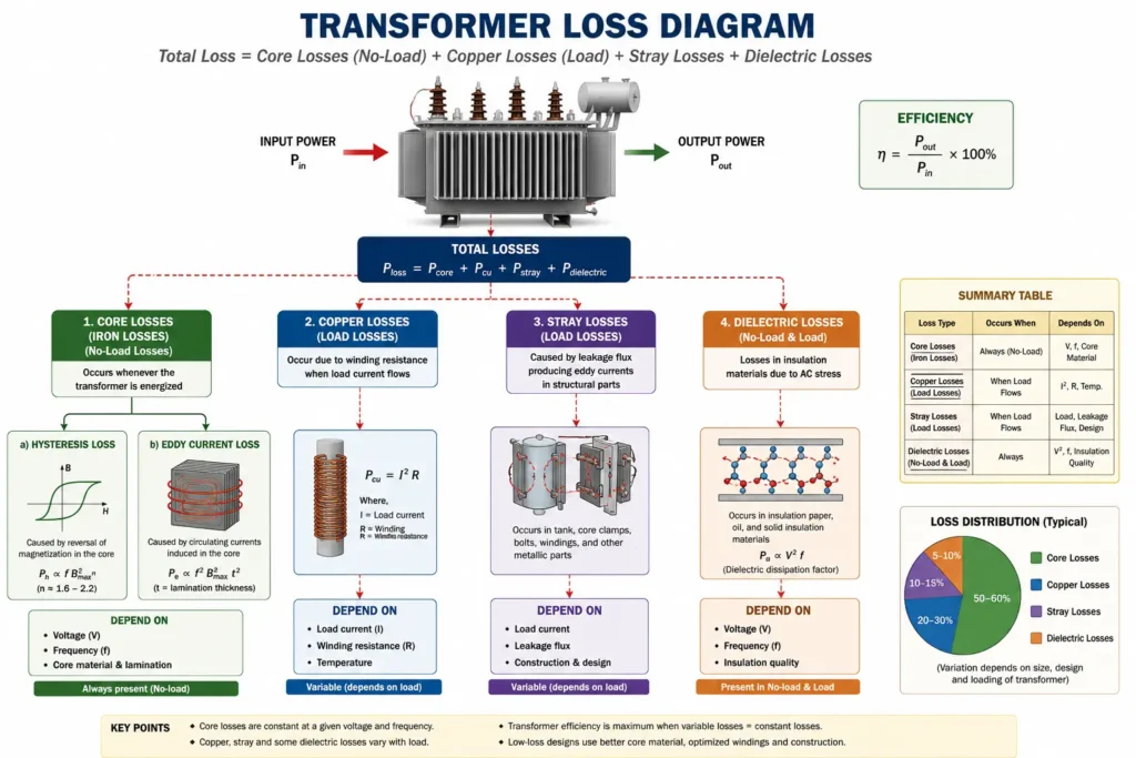
Transformer losses directly affect efficiency and operating cost.
1. Core Losses (Iron Losses)
Core losses occur continuously whenever the transformer is energized.
Types of Core Losses
Hysteresis Loss
Caused by repeated magnetization reversal in the core.
Eddy Current Loss
Induced circulating currents inside the core laminations.
Reduction Methods
- Thin laminations
- CRGO steel
- Amorphous cores
2. Copper Losses
Copper losses occur due to winding resistance.
Pcu=I²*RWhere:
- I = Current
- R = Winding resistance
Copper losses increase with load.
3. Stray Losses
Produced by leakage flux inducing currents in metallic components.
4. Dielectric Losses
Occur within insulation materials under AC voltage stress.
Transformer Efficiency
Transformer Efficiency Formula
η=(Input Power/Output Power)×100
Distribution transformers typically achieve efficiencies between:
- 95%
- 99%
depending on design and loading.
Factors Affecting Transformer Efficiency
1. Load Level
Maximum efficiency usually occurs around 50% to 70% loading.
2. Operating Temperature
Higher temperatures increase winding resistance and copper losses.
3. Core Material Quality
High-grade core materials reduce no-load losses.
4. Harmonic Distortion
Nonlinear loads generate harmonics that increase losses.
Common Harmonic Sources
- Variable frequency drives (VFDs)
- UPS systems
- LED lighting
- Data centers
Transformer Losses Comparison Table
| Loss Type | Occurs When | Depends On | Reduction Method |
|---|---|---|---|
| Core Loss | Constantly energized | Voltage | Better core materials |
| Copper Loss | Under load | Current | Larger conductors |
| Stray Loss | Load conditions | Leakage flux | Improved design |
| Dielectric Loss | Energized | Insulation quality | Better insulation |
Distribution Transformer Protection Systems
Transformer protection is essential for preventing catastrophic failures and ensuring personnel safety.
1. Fuse Protection
Primary-side fuses protect against:
- Short circuits
- Severe overloads
2. Circuit Breakers
Used in larger installations for coordinated protection.
Common Protection Functions
| ANSI Code | Function |
|---|---|
| 50 | Instantaneous overcurrent |
| 51 | Time overcurrent |
| 87T | Differential protection |
| 49 | Thermal protection |
| 63 | Buchholz relay |
3. Buchholz Relay
Used in oil-filled transformers with conservators.
Detects:
- Internal faults
- Gas accumulation
- Oil movement abnormalities
4. Differential Protection
Compares primary and secondary currents.
If imbalance exceeds the setting, the relay trips the transformer.
5. Temperature Protection
Monitors:
- Oil temperature
- Winding temperature
Excessive heat can rapidly degrade insulation.
6. Surge Protection
Lightning and switching surges can damage transformers.
Protective Devices
- Surge arresters
- MOV arresters
- Shield wires
Transformer Grounding Requirements
Proper grounding improves:
- Personnel safety
- Fault clearing
- System stability
Common Grounding Methods
Solid Grounding
Direct connection to earth.
Resistance Grounding
Uses grounding resistors to limit fault current.
Reactance Grounding
Uses inductive reactance for current limitation.
NEC, IEC, and IEEE Standards
NEC Standards
The National Electrical Code (NEC) includes transformer installation requirements such as:
- NEC Article 450
- Grounding rules
- Overcurrent protection
- Ventilation requirements
IEC Standards
Relevant IEC standards include:
| Standard | Description |
|---|---|
| IEC 60076 | Power transformers |
| IEC 60296 | Transformer oils |
| IEC 60599 | Dissolved gas analysis |
IEEE Standards
Important IEEE references:
| Standard | Purpose |
|---|---|
| IEEE C57 Series | Transformer standards |
| IEEE C57.91 | Loading guide |
| IEEE C57.104 | Oil diagnostics |
Engineering Example: Distribution Transformer Sizing
Example Scenario
An industrial facility requires:
- Total load = 320 kVA
- Future expansion = 20%
- Power factor = 0.9
Step 1: Include Expansion Margin
320×1.2=384 kVA
Step 2: Select Standard Rating
Choose:
- 400 kVA transformer
Step 3: Verify Voltage
Primary:
- 13.8 kV
Secondary:
- 480/277 V
Step 4: Determine Cooling
For continuous industrial loading:
- ONAN or ONAF cooling
Practical Applications of Distribution Transformers
Residential Networks
Provide 120/240 V or 230/400 V supply to homes.
Commercial Buildings
Used for:
- HVAC systems
- Lighting
- Elevators
- IT infrastructure
Industrial Plants
Supply motors, process equipment, and heavy machinery.
Renewable Energy Systems
Transformers integrate:
- Solar farms
- Wind turbines
- Battery storage systems
Data Centers
Dry-type transformers are often preferred due to reduced fire hazards.
Common Distribution Transformer Failures
1. Insulation Breakdown
Caused by:
- Aging
- Moisture
- Overheating
2. Overloading
Continuous overload operation accelerates insulation degradation.
3. Oil Contamination
Moisture and oxidation reduce dielectric strength.
4. Lightning Damage
High transient voltages can puncture insulation.
5. Loose Connections
Create hot spots and localized overheating.
Common Installation Mistakes
Incorrect Grounding
Improper grounding creates dangerous touch voltages.
Poor Ventilation
Restricts heat dissipation and reduces transformer lifespan.
Undersized Protection Devices
May fail to isolate faults correctly.
Ignoring Harmonic Loads
Can cause excessive heating in neutral conductors and windings.
Improper Cable Terminations
Loose terminations increase resistance and hot spots.
Distribution Transformer Maintenance
Preventive maintenance significantly extends transformer life.
Recommended Maintenance Tasks
Visual Inspection
Check for:
- Oil leaks
- Corrosion
- Discoloration
- Noise
Oil Testing
Perform:
- Dielectric breakdown test
- Moisture analysis
- Dissolved gas analysis (DGA)
Thermographic Inspection
Infrared scanning identifies abnormal hot spots.
Insulation Resistance Testing
Use a megohmmeter to evaluate insulation integrity.
Cleaning
Remove:
- Dust
- Moisture
- Contaminants
Safety Considerations
Working with distribution transformers involves serious electrical hazards.
Essential Safety Practices
1. Lockout/Tagout (LOTO)
Always isolate equipment before maintenance.
2. Use Proper PPE
Recommended PPE includes:
- Arc-rated clothing
- Insulated gloves
- Face shields
- Safety boots
3. Verify Absence of Voltage
Always test before touching conductors.
4. Follow Arc Flash Procedures
Conduct arc flash studies according to:
- NFPA 70E
- IEEE 1584
5. Maintain Safe Clearance Distances
Observe NEC and IEC minimum approach distances.
Distribution Transformer vs Power Transformer
| Feature | Distribution Transformer | Power Transformer |
|---|---|---|
| Application | End-user distribution | Transmission systems |
| Voltage Level | Medium to low voltage | High voltage |
| Efficiency Optimization | Partial load | Full load |
| Location | Near consumers | Transmission substations |
| Size | Smaller | Larger |
Future Trends in Distribution Transformers
Smart Transformers
Include:
- IoT monitoring
- Remote diagnostics
- Predictive maintenance
Eco-Friendly Insulation Fluids
Natural esters are replacing mineral oils in many applications.
Digital Monitoring Systems
Modern transformers use:
- Online DGA monitoring
- Thermal sensors
- SCADA integration
FAQs About Distribution Transformers
1. What is the main purpose of a distribution transformer?
A distribution transformer steps down medium voltage to usable low voltage for homes, commercial buildings, and industrial facilities.
2. What is the difference between a power transformer and a distribution transformer?
Power transformers operate in transmission systems at high voltages, while distribution transformers supply end users at lower voltages.
3. What causes transformer losses?
Main causes include:
- Core losses
- Copper losses
- Stray losses
- Dielectric losses
4. Why is transformer oil important?
Transformer oil provides both electrical insulation and cooling.
5. What is ONAN cooling?
ONAN stands for Oil Natural Air Natural, where oil circulation and air cooling occur naturally without forced fans.
6. How long does a distribution transformer last?
With proper maintenance, a distribution transformer can operate for 25–40 years.
7. What is transformer efficiency?
Transformer efficiency is the ratio of output power to input power expressed as a percentage.
8. Which standards apply to distribution transformers?
Key standards include:
- NEC Article 450
- IEC 60076
- IEEE C57 Series
Conclusion
The Distribution Transformer remains one of the most essential devices in electrical power systems. From residential utility networks to complex industrial facilities, transformers ensure safe, efficient, and reliable voltage conversion for modern energy infrastructure.
Understanding transformer types, working principles, losses, cooling methods, protection systems, and maintenance requirements is critical for engineers, electricians, technicians, and plant operators.
As electrical systems evolve toward smart grids, renewable integration, and digital monitoring, distribution transformers are becoming more intelligent, efficient, and environmentally sustainable.
Proper sizing, protection coordination, grounding, and preventive maintenance are essential for maximizing transformer lifespan and minimizing costly downtime.
For professionals working in electrical engineering and industrial power systems, mastering transformer fundamentals is no longer optional—it is a core technical competency.