
Voltage Drop Calculation in Distribution Networks Explained (2026 Guide)
Last updated: May 16, 2026
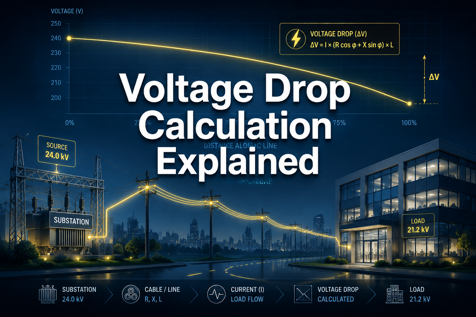
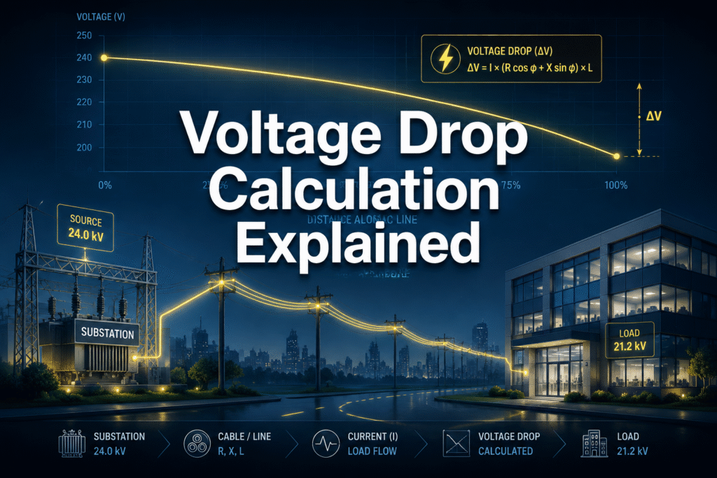
A voltage drop calculation determines the amount of electrical potential lost as electricity travels from a power source to the load. This calculation is critical for electricians to ensure that equipment receives adequate power to operate safely and efficiently, preventing performance issues, overheating, and potential damage to sensitive electronics.
Table of Contents
Key Takeaways
- What it is: Voltage drop is the reduction in electrical voltage along the path of a current.
- Why it matters: Excessive voltage drop can cause lights to flicker, motors to overheat and fail, and electronic equipment to malfunction or shut down.
- Primary Causes: The main factors are conductor resistance, the total length of the circuit, and the amount of current (amperage) flowing through it.
- Acceptable Limits: The National Electrical Code (NEC) generally recommends a maximum voltage drop of 3% for individual branch circuits and 5% for the total feeder and branch circuit combined.
- The Formula: The basic formula for single-phase voltage drop is
VD = 2 x K x I x D / CM, where K is the conductor’s resistivity, I is current, D is distance, and CM is the wire’s circular mils. - Mitigation: Solutions include using a larger gauge wire (lower resistance), shortening the circuit length, or reducing the load on the circuit.
- Safety First: Proper voltage drop calculation is not just about performance; it’s a fundamental aspect of designing safe and reliable electrical systems.
What Exactly Is Voltage Drop and Why Does It Matter?
Voltage drop is the loss of electrical pressure (voltage) in a circuit as electricity travels from the power source to the end device. Every wire has some internal resistance, and as current flows through this resistance, a small amount of voltage is lost as heat. For electricians and system designers, this isn’t just a trivial number; it’s a critical indicator of an electrical system’s health and efficiency.
A mere 5% voltage drop can reduce the light output of an incandescent bulb by nearly 17% and cause an induction motor’s torque to fall by 19%. This loss of performance can lead to equipment inefficiency, premature failure, and increased energy costs. Properly calculating and accounting for voltage drop ensures that appliances and machinery receive the voltage level specified by the manufacturer for safe and effective operation.
Key Insight: Think of voltage like water pressure in a hose. A long, thin hose (high resistance wire) will have a weak trickle at the end, while a short, wide hose (low resistance wire) will deliver a powerful stream. The goal of a voltage drop calculation is to ensure the « pressure » at the end of the line is strong enough to do the job.
What Are the Main Causes of Voltage Drop?
The primary causes of voltage drop are directly related to the physical properties of the electrical circuit. Understanding these three core factors is the first step toward performing an accurate voltage drop calculation and designing a robust system.
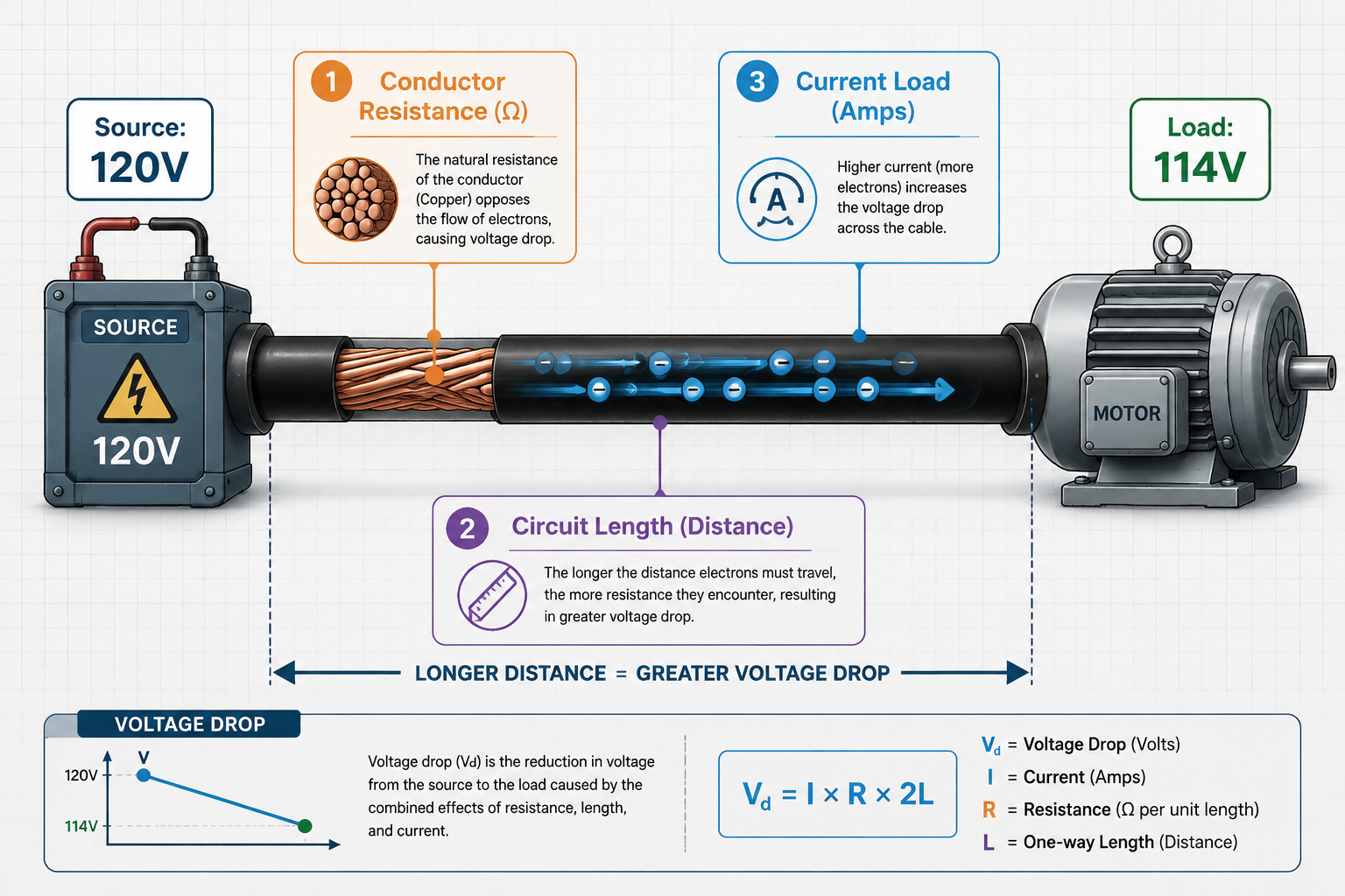
The three main culprits behind voltage drop are:
- Conductor Resistance: Every material has a natural resistance to electrical flow. Materials like copper and aluminum are used because they have very low resistance, but it’s not zero. Thicker wires have less resistance than thinner wires, just as a wider pipe allows more water to flow. The material itself (e.g., copper is less resistive than aluminum) also plays a significant role.
- Conductor Length: The farther electricity has to travel, the more voltage is lost. This is a linear relationship—doubling the length of the wire will double the voltage drop, assuming all other factors remain constant. This is why long extension cords are a common source of voltage drop issues for power tools.
- Current (Load): The amount of current (measured in amperes or amps) flowing through the wire has a direct impact. A higher current will produce a greater voltage drop. This is why a circuit powering a heavy-duty motor will experience a more significant drop than one powering a single LED light.
How Do You Perform a Basic Voltage Drop Calculation?
A basic voltage drop calculation uses a standard formula to estimate the voltage loss in a simple circuit. For most common applications, especially for DC or single-phase AC circuits, a simplified formula provides a reliable estimate that is essential for proper wire sizing and system design.
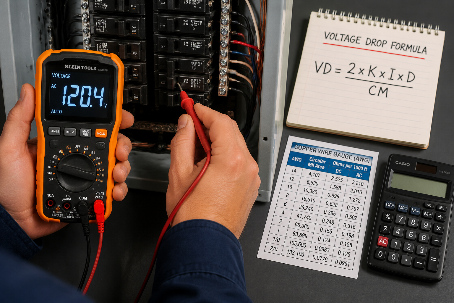
The most common formula for a single-phase circuit is:
VD = (2 x K x I x D) / CM
Where:
- VD = Voltage Drop (in volts)
- 2 = This factor accounts for the two wires in a single-phase circuit (one for supply, one for return).
- K = The resistivity of the conductor material (a constant). For copper, it’s approximately 12.9 ohms per mil-foot at 75°C. For aluminum, it’s about 21.2.
- I = The current flowing through the circuit (in Amps).
- D = The one-way distance from the source to the load (in feet).
- CM = The cross-sectional area of the conductor (in Circular Mils). You can find this value in NEC Chapter 9, Table 8.
Worked Example
Let’s say you are running a 120V single-phase circuit to a 15-amp load that is 150 feet away, using a 12 AWG copper wire.
- K = 12.9 (for copper)
- I = 15 Amps
- D = 150 feet
- CM = 6,530 (for 12 AWG wire, from NEC table)
Calculation:VD = (2 x 12.9 x 15 x 150) / 6,530VD = 57,050 / 6,530VD ≈ 8.89 Volts
The voltage at the device would be 120V - 8.89V = 111.11V. To find the percentage drop:%VD = (8.89V / 120V) * 100 ≈ 7.4%
Common Mistake: A 7.4% drop is well above the recommended 3% for a branch circuit. This indicates a problem. To fix this, the electrician would need to use a larger wire (e.g., 10 AWG or 8 AWG) to reduce the resistance and bring the voltage drop within acceptable limits.
What Are the Acceptable Voltage Drop Limits?
Acceptable voltage drop limits are industry standards, primarily defined by the National Electrical Code (NEC), that dictate the maximum permissible voltage loss in a circuit. These guidelines ensure that electrical equipment operates correctly and safely. Adhering to these limits is a core responsibility for electricians.
According to the NEC, the generally accepted limits are:
- Branch Circuits (NEC 210.19(A) Informational Note No. 4): The voltage drop should not exceed 3% at the farthest outlet for power, heating, and lighting loads.
- Feeder + Branch Circuit (NEC 215.2(A)(1) Informational Note No. 2): The total combined voltage drop for both the feeder and the branch circuit should not exceed 5%.
| Circuit Type | Recommended Max Drop | Example (120V System) | Example (480V System) |
|---|---|---|---|
| Branch Circuit | 3% | 3.6 Volts | 14.4 Volts |
| Feeder + Branch | 5% | 6.0 Volts | 24.0 Volts |
It’s crucial to remember that these NEC notes are recommendations, not mandatory rules. However, they are widely adopted as the industry standard for good reason. Exceeding these limits can lead to poor performance and safety hazards. Some sensitive electronic equipment may even require stricter limits, so always check the manufacturer’s specifications.
A Simple Voltage Drop Calculator
Use this interactive calculator to get a quick estimate for your next voltage drop calculation. Enter your circuit parameters to see the estimated voltage loss and determine if it falls within acceptable limits.
Voltage Drop Calculator
How Can You Mitigate Excessive Voltage Drop?
If your voltage drop calculation reveals an excessive loss, you must take corrective action. Mitigating voltage drop involves adjusting one of the core factors in the formula to reduce resistance or shorten the electrical path.
Here are the most effective methods to correct high voltage drop:
- Increase Conductor Size: This is the most common solution. Using a thicker wire (a lower AWG number) decreases its circular mil resistance, allowing current to flow more easily. This directly reduces the voltage drop. For example, upgrading from a 12 AWG wire to a 10 AWG wire can make a significant difference on a long run.
- Shorten Conductor Length: While you can’t always move the equipment closer to the panel, careful planning during the design phase can minimize wire runs. Avoid unnecessary loops or indirect routing.
- Reduce the Load on the Circuit: If possible, decrease the amount of current on the circuit. This could mean splitting the load across multiple circuits or using more energy-efficient appliances that draw less power.
- Increase the Source Voltage: In some industrial or commercial applications, it’s more efficient to distribute power at a higher voltage (e.g., 480V instead of 208V) and then use a transformer to « step down » the voltage near the equipment. Since power (Watts) is voltage times current, a higher voltage allows the same amount of power to be delivered with less current, which significantly reduces voltage drop (VD is directly proportional to current).
- Parallel Conductors: For very heavy loads or extremely long runs, electricians may run two or more smaller conductors in parallel. This effectively creates one larger conductor, increasing the total circular mils and reducing the overall resistance.
Conclusion: A Foundation of Electrical Safety and Efficiency
Mastering the voltage drop calculation is more than an academic exercise; it’s a fundamental skill that separates amateur work from professional, safe, and efficient electrical installations. By understanding the core causes—conductor resistance, length, and current—and applying the correct formulas, electricians can ensure that every component in a distribution network receives the power it needs to perform optimally.
Failing to account for voltage drop leads to underperforming equipment, wasted energy, and potential safety hazards. By following NEC guidelines and using the mitigation strategies outlined here, you can design and implement electrical systems that are not only compliant but also reliable and built to last.
Actionable Next Steps:
- Bookmark the NEC Tables: Keep a digital or physical copy of NEC Chapter 9, Table 8 (Conductor Properties) handy for quick access to circular mil values.
- Use a Calculator: For everyday work, use the interactive calculator on this page or a dedicated app to double-check your manual calculations.
- Always Upsize for Long Runs: If you are planning a circuit that is approaching 100 feet or more, perform a voltage drop calculation before purchasing the wire. It’s very likely you will need to use a larger gauge than the minimum required for the amperage alone.
Frequently Asked Questions (FAQ)
1. What is the simplest formula for voltage drop?
For single-phase AC or DC circuits, the simplest and most common formula is VD = (2 x K x I x D) / CM, where K is material resistivity, I is current, D is distance, and CM is the wire’s circular mils.
2. Why is there a ‘2’ in the single-phase voltage drop formula?
The ‘2’ accounts for the total length of the circuit path. Electricity must travel from the source to the load and then return to the source, so the total distance is twice the one-way length.
3. Does voltage drop waste electricity?
Yes. The voltage lost in the conductor is converted into heat due to the wire’s resistance. This heat is wasted energy, which is why oversized voltage drop can lead to higher electricity bills.
4. Can voltage drop damage electronics?
Absolutely. Sensitive electronics are designed to operate within a specific voltage range. Voltages that are too low (a « brownout » condition) can cause logic circuits to fail, power supplies to overheat, and motors to stall, leading to permanent damage.
5. What is the difference between the voltage drop calculation for single-phase and three-phase power?
The single-phase formula uses a multiplier of 2. The three-phase formula uses a multiplier of √3 (approximately 1.732) because the return currents partially cancel each other out in a balanced system, resulting in less voltage drop for the same load.
6. Does temperature affect voltage drop?
Yes. As a conductor’s temperature increases, its resistance also increases. The standard ‘K’ value is often given at 75°C (167°F). In very hot environments or when wires are bundled together, you may need to use a temperature correction factor for a more precise calculation.
7. Is voltage drop the same as line loss?
The terms are often used interchangeably. Line loss typically refers to the total power (in watts) lost in the line, while voltage drop refers specifically to the loss of voltage. They are directly related by the formula P = V x I.